Other Parts Discussed in Thread: LMK04208
Tool/software:
Hello,
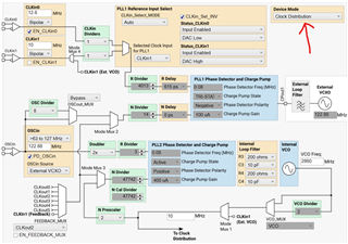
I have a question about the SYNC input functionality on the LMX2594. From what I understand, this input is used to synchronize the phase of multiple LMX2594 devices. In my setup, I’m working with the ZCU111 board from AMD/Xilinx, which includes both the LMK04208 and LMX2594 clocking ICs.
On the ZCU111 board, the MUXout pin of the LMX2594 is connected to an onboard LED and is configured to indicate PLL lock status. When the board is running normally, the LEDs are lit, showing that the PLLs are locked and the board is functioning as expected.
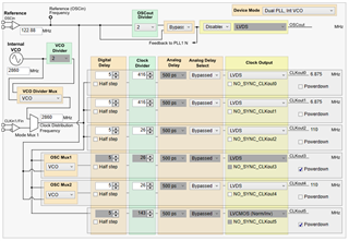
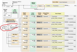
However, I noticed that the SYNC signal from the LMK04208 (coming out on CLKout3) was not active. Please refer to the attached figure that illustrates the ZCU111 clocking structure.
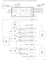
Interestingly, when I enabled CLKout3 and set its frequency to 110 MHz (the same as CLKout4), the LEDs turned off, suggesting that the lock detector now indicates a non-locked state for the LMX2594 PLLs.
Could you please help me understand why enabling CLKout3 affects the lock status in this way? Are there any additional configurations that I need to enable on the LMX2594?
I tried enabling VCO_PHASE_SYNC and setting INPIN_IGNORE to zero, but it did not work.
My goal is to enable the SYNC signal so that I can synchronize the LMX2594 PLLs using a 10 MHz reference input connected to CLKin1 of the LMK04208.
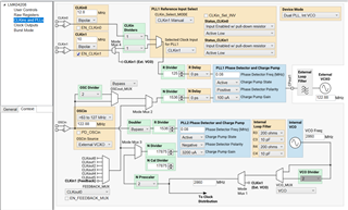
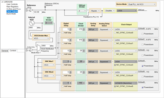
I’ve attached my configuration files for both the LMK04208 and LMX2594 as generated by TICSPro for your reference.
Thank you in advance for your support!
LMK_CLKout4_110MHz_CLKin1_10MHz_CLKout3_110MHz.tcsLMX_3520MHz.tcs