


Other Parts Discussed in Thread: LMX2592,
Tool/software:
hello everyone.
I have design a pcb board use lmx2592 to generate signal.
Is lmx2592 pin compatiable with lmx2594??
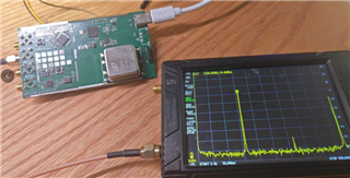
In same PCB,the output frequency of LMX2592 is accurate.But the output freq of LMX2594 have bigfrequency deviations.
and the deviations is not fixed.
for example
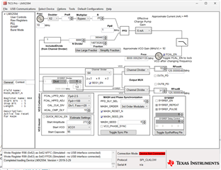
the loop filter parameter is the same as lmx2592 which is work fine.
here is my test code:
#include "lmx2594.h"


#include "stm32f0xx.h"

unsigned int LMX2594_Reg[113]=
{
	0x0000,
0x0000,
0x0000,
0x0000,
0x0000,
0x0000,
0x0001,
0x0001,
0x0064,
0xFFFF,
0x3FFF,
0x0011,
0x0064,
0x0000,
0xB000,
0x0888,
0x0000,
0x0000,
0x0000,
0x0000,
0x0000,
0x0000,
0x0000,
0x0000,
0x0000,
0x0000,
0x0000,
0x0000,
0x0001,
0x0000,
0x0000,
0x0001,
0x0000,
0x0200,
0x00BF,
0x0000,
0x000C,
0x0A40,
0x0000,
0x003F,
0x0001,
0x0081,
0xC350,
0x0000,
0x03E8,
0x0000,
0x01F4,
0x0000,
0x1388,
0x0000,
0x0322,
0x00A8,
0x0000,
0x0001,
0x8001,
0x0020,
0x0000,
0x0000,
0x0000,
0x0000,
0x0820,
0x0080,
0x0000,
0x4180,
0x0300,
0x0300,
0x07FC,
0xC0DF,
0x0A23,
0x8000,
0x0005,
0x0000,
0x0000,
0x8001,
0x53E2,
0x8304,
0x1F40,
0x0004,
0x0000,
0x1E21,
0x0393,
0x43EC,
0x318C,
0x318C,
0x0488,
0x0002,
0x0DB0,
0x0624,
0x071A,
0x007C,
0x0001,
0x0401,
0xC848,
0x27B7,
0x0064,
0x0110,
0x0080,
0x064F,
0x1E40,
0x4000,
0x5001,
0x0148,
0x10D8,
0x1604,
0x2000,
0x40B2,
0xC802,
0x00C8,
0x0A43,
0x0642,
0x0500,
0x0808,
0x2478,

};
static void DELAY_Nop(uint32_t num)
 {
 	while(num--)
	{
 		__NOP();
	}
 }


void LMX2594_Init()
{
	unsigned int y=0,j;


	LmxWrite(0,0x0002);//soft reset
	DELAY_Nop(500);
	LmxWrite(0,0x0000);//cancel reset
	DELAY_Nop(500);
	DELAY_Nop(500);
	DELAY_Nop(500);

//	VCO_Caliberation();
	for(y=113;y>6;y--)
	{
		LmxWrite(113-y,LMX2594_Reg[y-1]);
	DELAY_Nop(100);
		j=lmxRead(113-y);

		/*while(j!=LMX2594_Reg[y-1])
		{
			//WDT_CONTR=0x25;//?????
			LMX2594_TXData(113-y,LMX2594_Reg[y-1]);
			j=LMX2594_RXData(113-y);
		}
		//WDT_CONTR|= 0x10;//??*/
	}
//	WDT_CONTR= 0x00;//????
	DELAY_Nop(5000);
 //delay_ms(10);  //??10ms

 //lmx.R0.FCAL_EN=1;   //??FCAL_EN=1????????R0,???VCO?????????
 LmxWrite(0,0x2478);//lmx_wr(0,lmx.R0.REG0);

}
any suggestion please

