A related question is a question created from another question. When the related question is created, it will be automatically linked to the original question.
If you have a related question, please click the "Ask a related question" button in the top right corner. The newly created question will be automatically linked to this question.
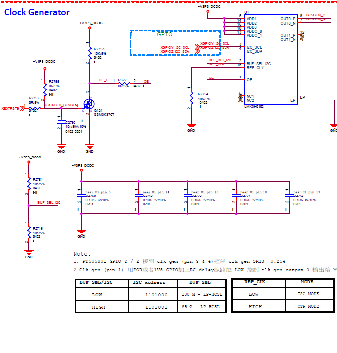
OE# (Pin 1): The reference design uses a 3.9kΩ pull-down resistor to ground. Since this value is quite specific, we would like to ask what the internal pull-down resistance is. Can it be changed from 3.9kΩ to 10kΩ?
Curious about the reason why Pin6/Pin9 (NC pins) have output — would reserving test points for these two pins be helpful for debugging?
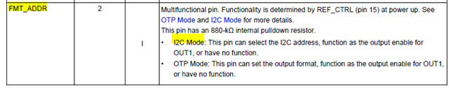
If IC2 Mode is selected (REF_CTRL pulled down), what is the default output impedance of the CLK GEN after power-on but before I2C communication starts? Is it 100 ohms? 85 ohms? What is the impedance tolerance? e.g., ±5%