Other Parts Discussed in Thread: DS250DF410
Tool/software:
I'm trying to use the LMK04832 to generate a 1.611328125GHz Clock.
I'm targeting using LVPECL 1600 Format at the Output of the LMK04832.
The 1.611328125GHz Clock {LMK Output] is AC-Couple to a DS250DF410's Rx Input Port.
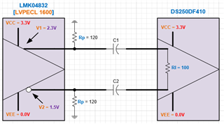
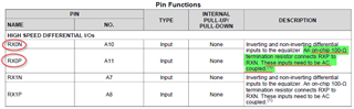
Data Sheet for DS250DF410 shows Pin Function Table, noting 100Ohm Termination and AC-Coupling Requirements.

The LMK04832 Data Sheet shows the Output Voltage to be 800mV when DC-Coupling is used:
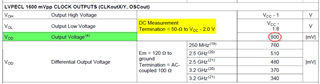
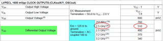
The LMK04832 Data shows that the Output Voltage "Varies" as a Function of Frequency when AC-Coupling is used:
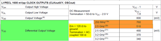
At 250MHz, Vod = 760mV.
At 2.5GHz, Vod = 510mV.
I've tried to analyze that these are the "Expected" Voltages at the Output of the LMK04832 when AC-Coupling is used, but I'm not getting consistent results.
A). Analysis
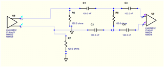
The AC-Coupling Capacitor and the 100Ohm Internal Termination of the DS250F410, form an Active Voltage Divider that can be modeled as shown:
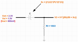
If I select C = 220pF and f = 250MHz, I get:
Xc = [(1)/(2)*(Pi)*(250MHz)*(220pF)] = 2.8937
So, V2 = V1 * [(50)/(50 + 2.8937)]
When V1 = 2.3V [Voh from LMK], then V2 = 2.174V
When V1 = 1.5V [Vol from LMK], then V2 = 1.418V
So, V2 = 2.174V - 1.418V = 756mV [Data Sheet says 760mV].
If I select C = 220pF and f = 2.5GHz, I get:
Xc = [(1)/(2)*(Pi)*(2.5GHz)*(220pF)] = 0.28937
So, V2 = V1 * [(50)/(50 + 0.2897)]
When V1 = 2.3V [Voh from LMK], then V2 = 2.287V
When V1 = 1.5V [Vol from LMK], then V2 = 1.491V
So, V2 = 2.287V - 1.491V = 796mV [Data Sheet says 510mV].
As you can see, I'm getting results that match the Data Sheet at 250MHz Output [With C = 200pF], but 'Not' at 2.5GHz!
Question: Could you provide the Math Steps used to obtain the Vod Values in the LMK04832 Data Sheet when AC-Coupling is used with a 100Ohm Termination?