This thread has been locked.

If you have a related question, please click the "Ask a related question" button in the top right corner. The newly created question will be automatically linked to this question.

LMK5B12204: Synchronization between multiple DPLL among APLL1 and APLL2 output

Part Number: LMK5B12204
Other Parts Discussed in Thread: LMK05318B, , LMK5C23208A, LMK5B12212

Tool/software:

Hello,

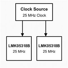
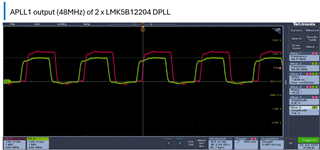
We are using mentioned DPLL part as clock generator to generate different frequencies from APLL1 and APLL2 output. APLL1 will be 48 MHz and APLL2 will be 25 MHz.

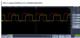
Requirement is that we will have multiple DPLL chips each generating above mentioned frequencies with synchronization. There will be 25MHz or 125MHz clock connected to PRIREF input of DPLL and 25 MHz oscillator to XO input. We require that multiple DPLL APPL1 output should be synchronized with each other and similarly for APLL2. 

Please let us know if this is achievable / feasible with this part?

Also, is there any way to fix the phase delay of APLL1 and APLL2 output with PRIREF input clock?

Thank you!

  • Hi Ajay,

    #1

    25 MHz XO input is not recommended because it has an integer relationship to the BAW VCO (2500 MHz). A fractional relationship is required to allow the DPLL to operate in fractional-N divider mode. Also, to avoid integer-boundary spurs on the outputs.

    Instead, please use frequencies that are fractional to the BAW VCO such as 24 MHz, 27 MHz, 38.88 MHz, 48 MHz, 54 MHz.

    #2

    Update the frequency plan to APLL1 is 25 MHz and APLL2 is 48 MHz since APLL1 is centered at 2500 MHz.

    #3

    Besides #1 and #2, the intended use case is possible with the LMK5B12204. There is also the 8-output version of this part, LMK05318B, if you need more outputs and less devices.

    Regards,

    Jennifer

  • Hi Jennifer,

    Thanks for your quick response.

    Noted on frequency plan at APLL1 and APLL2. Will test it out. However, we needed low jitter at 48MHz because we will be using it to clock ADC, DAC and as per datasheet APPL1 output have less jitter than APLL2 output. Share your thoughts.

    Thanks for confirming on use case requirement. We will again check it out because as per current observations APPL output of multiple DPLL are in sync but at random phase difference which varies on every reboot. We have not confirmed LoFL and LoPL is locked which we will verify again.

    Please see some attached images below for your reference and request to help us understanding reasons and steps to Sync on rising edge at every reboot.

    Setup Image:


    Thanks,

    Ajay.

  • Hi Ajay,

    1. Please do confirm the DPLL is locked in your tests (LOFL and LOPL status registers are 0).
    2. Do you need 0 delay between input and output at every power up? Or do you only need deterministic phase delay between in and out across power ups (meaning there is a fixed offset that stays constant between power ups)?
      1. If any of these are true, then you can use the LMK5C23208A which supports deterministic delay between input and output as well as a feature to zero-out the input-to-output delay by a programmable phase offset register.

    Regards,

    Jennifer

  • Hi Jennifer,

    Yes, we had verified LoFL and LoPL and still we see the offset between APLL output of two DPLL devices.

    Below two images are of APLL1 output 25MHz.


    Also, below are random phase difference we get on every power reboot.


    Power reset

    Phase 

    Delay

    1

    96.65

    10.76 ns

    2

    -2.266

    -261.4 ps

    3

    147.9

    16.43 ns

    4

    91.3

    10.17 ns

    5

    56.59

    6.354 ns

    6

    154.5

    17.17 ns

    7

    -153.9

    -17.09 ns

    8

    -54.23

    -6.018 ns

    9

    10.19

    1.166 ns

    10

    -176.3

    -19.56 ns

    So, while debugging we found that on every boot, there is random delay between input 25MHz and output 25MHz. So, please let us know reason of this.

    This behavior explains why APLL output of both DPLL are not in sync even though LoPL and LoFL are locked.

    Thanks, on your suggestion of LMK5C23208A. This means issue we see in existing part can be resolved in LMK5C23208A ?

    Thanks,

    Ajay

  • Hi Ajay,

    I am reviewing your comments.

    Regards,

    Jennifer

  • Hi Jennifer,

    Any update?  Thanks!

    Regards,

    Ajay

  • Hi Ajay,

    Thank you for your patience as there was a TI US holiday that passed this weekend.

    1. Can you please share your tcs file? If you only have one input coming in (25 MHz), then is the DPLL disabled? Are you using an XO input of 48 MHz with a REF input of 25 MHz?
    2. In your current setup diagram, the outputs may not have the same phase alignment. However, the outputs ARE phase synchronized to the input clock when the device is locked. When locked, the outputs have a near 0 frequency error between input and output. Also, the outputs continuously follow the input by a small fixed phase offset. This small fixed phase offset can vary across devices and across power-ups. That is why you are not seeing phase alignment between multiple devices.
    3. What it seems you want is #1 deterministic delay to ensure the same phase across power-ups and #2 zero delay to ensure phase alignment between outputs of other devices.
      1. The LMK05318B does not support deterministic delay which means multiple output phase alignment is not supported.
      2. The LMK5C2308A or LMK5B12212 does support deterministic delay. Two achieve phase alignment between multiple devices, enable the DPLL and configure ZDM on each device. Each device must synchronize to the same reference (25 MHz). With ZDM, the input-to-output phase offset is deterministic which means it can be "zeroed out" using the DPLLx_PH_OFFSET register. Once you know how much offset there is, the register can be configured such that the offset between input and output is near 0. In the LMK5B12212/LMK5C23208A TICS Pro GUI you can see that the DPLLx_PH_OFFSET register is configurable based on the time delay between input and output:

    Let me know if you have further questions.

    Regards,

    Jennifer