This thread has been locked.

If you have a related question, please click the "Ask a related question" button in the top right corner. The newly created question will be automatically linked to this question.

LMK03318EVM: Programming LMK03318 on the EVM with USB2ANY

Part Number: LMK03318EVM
Other Parts Discussed in Thread: LMK03318, USB2ANY

Tool/software:

Hi Derek,

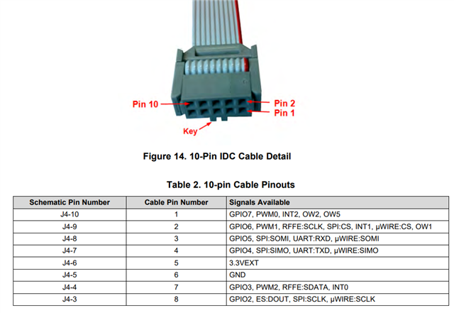
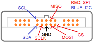
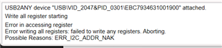
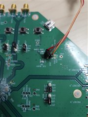
I de-popped the 0 Ohm R166 and R167. However, I am still unable to program the LMK03318 with external USB2ANY Dongle. I am using jumper wires for the I2C connection. Pics attached:
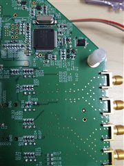
Thanks,

Prasoon

  • Prasoon,

    Just to rule out anything other than the USB2ANY being an issue - are you seeing successful communication with the on-board USB2ANY when R166 and R167 are connected?

    Thanks,

    Kadeem

  • Hi Kadeem,

    Yes, I have been able to program, successfully, with the onboard USB2ANY in the past with the R166 and R167 connected.

    Prasoon

  • Is there a way to test USB2ANY for correct functionality?

  • Prasoon,

    It should just be as simple as removing those resistors and soldering in the cables in the correct locations (ensure that the USB2ANY-side wires are connected to the correct pins).

    If you probe the SDA and SCL with an oscilloscope on the board side with the off-board USB2ANY, do you see the I2C signals properly reaching the board?

    Thanks,
    Kadeem

  • Kadeem,

    I monitored SDA and SCL, on an oscilloscope, from the off board USB2ANY while USB2ANY was scanning the I2C bus using the TICS Pro. I didn't see any waveform show up on the scope. Can I return the off board USB2ANY for an evaluation?

    Thanks,

    Prasoon

  • Prasoon,

    Yes - though also check to make sure that the USB2ANY pins, without connection to the board, are or are not toggling before performing a return.

    Thanks,
    Kadeem

  • Hi Kadeem,

    Yes, I measured without connecting to the LMK EVM board. Maybe I will also measure with the 30 pin cable coming off the USB2ANY, to rule out the cable.

    Thanks.

  • Kadeem,

    I checked the SDA, SCL and GND pins of the 10 pin USB2ANY header and they showed end-to-end continuity on the DMM. So, if something is wrong on the USB2ANY it looks like it may be the dongle.

    Prasoon

  • Prasoon,

    To be clear - you are saying that the header on the evaluation module, when using the on-board, is seeing no issues? Or that the USB2ANY dongle, when probing the pins directly, is seeing no issues? 
    You have the correct orientation for checking the pins with the dongle, shown below?

    Is TICS Pro recognizing the dongle when connected (DemoMode not being selected for the communication interface)?

    Thanks,
    Kadeem

  • When you're probing I2C lines, do you see any bus transactions at all? This is something you want to look at on an oscilloscope, so you can check if you see any transaction at all. If you don't see logic HIGH at idle and at least an attempt at generating the slave address by the USB2ANY, you likely do not have the right pins.

    This cable diagram is confusing, because the cable pin number and the schematic pin number are opposite of each other, leading to perpetual confusion about which pins connect to where. I have an updated diagram that shows where on both the cable and the USB2ANY the relevant signals are located. The BLUE pins show the correct connections. Please ensure that you have the right jumper wires connected on the USB2ANY itself - if I had a nickel for every time I had this backward, I'd retire today.

    If you're certain you have the right pins and you don't have any signal coming out of them, it's possible the pins on the microcontroller in the USB2ANY external box are damaged.

    One other theory: looking over the EVM schematic, I also note that there are several current sense amplifiers dependent on the 3.3V rail for operation. It's a long-shot, but maybe these must be powered to operate the LMK03318 correctly. You could try connecting the on-board USB to any standard charging port or a different machine, and see if the external I2C works that way - if so, it indicates a dependence on the on-board 3.3V supply derived from the USB circuit.

  • I see. Ok. I have, most certainly, been using the wrong pins if the annotated diagram above is correct. Let me re-try.

  • Ok. That was it. I confused the the J4 pin numbers with the cable pin numbers. Thanks for explaining this to me, patiently, yet again.