This thread has been locked.

If you have a related question, please click the "Ask a related question" button in the top right corner. The newly created question will be automatically linked to this question.

CDCE6214: Clock & timing forum

Part Number: CDCE6214


Tool/software:

Hi, 

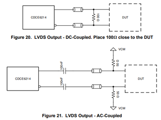
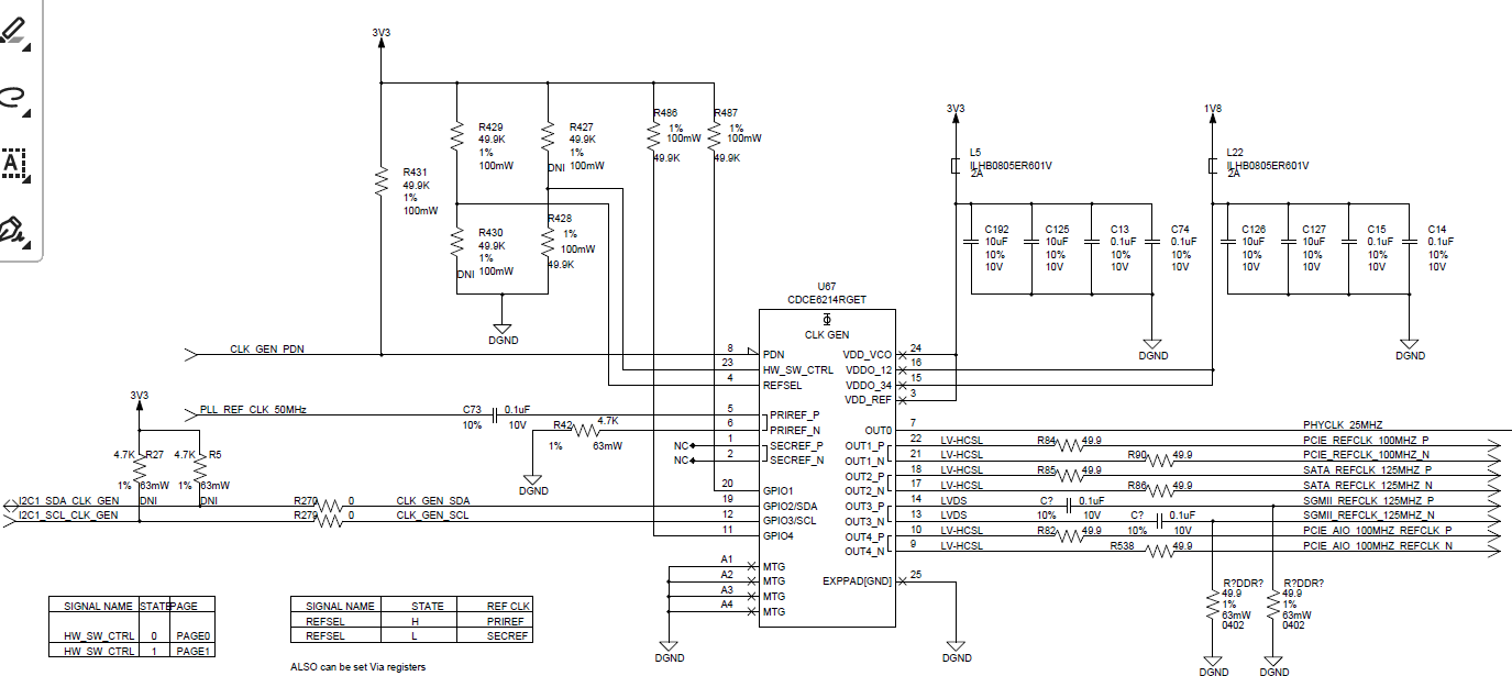
We are using CDCE6214 for our current project. Can you please verify the below circuit and provide your feedback.

Thanks, 

Vishal K

  • Hello,

    The team is OOO for U.S. holiday today. Please expect a delay in response.

  • Vishal,

    1. The SDA and SCL pullup resistors must be populated, if not on the CDCE6214 side then on the I2C host side at a minimum.
    2. We recommend using separate ferrite beads for VDDO_12 and VDDO_34, as the frequencies are not the same between these outputs.
    3. Where are there series 50-Ohm resistors for LP-HCSL outputs - what is the intended behavior here?
    4. The LVDS outputs should be connected one of the two ways shown here, not connected to GND through 50-Ohm resistors.

      Note that in the AC-LVDS use case, the 50-Ohm resistors are to the common mode voltage.

    Thanks,

    Kadeem

  • Hi Kadeem, 

    Thanks for your feedback. 

    See below are my response on your feedback:

    1. The SDA and SCL pullup resistors must be populated, if not on the CDCE6214 side then on the I2C host side at a minimum.-----Its present on host side.
    2. We recommend using separate ferrite beads for VDDO_12 and VDDO_34, as the frequencies are not the same between these outputs.-----Shall i combine same frequency for VDDO_12 and use one ferrite bead ? please 
    3. Where are there series 50-Ohm resistors for LP-HCSL outputs - what is the intended behavior here?---- Please look into schematic all LP-HCSL line has 50-Ohm series resistor
    4. The LVDS outputs should be connected one of the two ways shown here, not connected to GND through 50-Ohm resistors.----Output 3 is used for LVDS, Ac caps with shunt 50- Ohm res are available and connected to ground. please recheck the schematic

    Thanks, 

    Vishal K 

  • Vishal,

    1. For the best jitter performance, I would recommend swapping OUT2 and OUT4 and using separate ferrite beads for VDDO_12 vs VDDO_34. The current configuration will have much worse output-output crosstalk.
    2. LP-HCSL does not require these resistors. I do not see a reason why these should be 50-Ohm resistors. 0-Ohm resistors would be suitable, if a resistor were to be populated at all.

    Thanks,

    Kadeem

  • Hi Kadeem, 

    Thanks for the feedback.

    Point number 1 will do the changes as per your recommendation 

    Point number 2 datasheet suggested to have series resistor for that only I kept 50ohm 

    Thanks,

    Vishal K  

  • Vishal,

    Point number 2 datasheet suggested to have series resistor for that only I kept 50ohm 

    Please change these to 0ohm resistors as per Kadeem's recommendation. The datasheet depicts having Rs in the event any additional impedance matching needs to be done. Having proper impedance matching prevents ring back on the clock signal.

    Best,

    Cris