This thread has been locked.

If you have a related question, please click the "Ask a related question" button in the top right corner. The newly created question will be automatically linked to this question.

LMK3H0102-Q1: PCIe Condition

Part Number: LMK3H0102-Q1

Tool/software:

Hi team,

My customer Bosch have some questions about PCIe CLK as below:

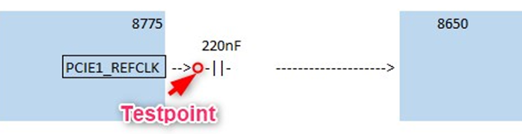
About PCIe clock from RC to EP, some applications use 220nF capacitors in series, while some use 0 ohm resistors. What conditions determine whether to connect a capacitor or a resistor?

2. Is the PCIE clock classified as voltage type or current type device? What type is usually used and how to know a specific device belongs to which type?

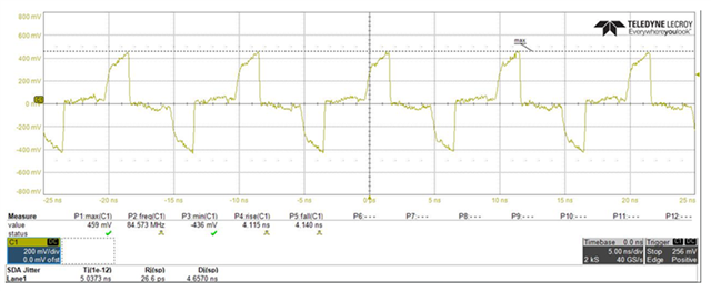
3. Can you please feedback some comment about the PCIe CLK waveform below? In which condition will lead to this results.

Best Regards,

Xiaowei Zhang

  • Xiaowei,

    1. Whether a capacitor or series resistor is used depends on the receiver specifications. If the receiver requires an AC-coupled clock, then the capacitor is needed. For standard PCIe, the most common connection is a 0-Ohm resistor.
    2. There are two similar types of output for PCIe, HCSL and LP-HCSL. HCSL requires an external 50-Ohm resistor to GND for driving the current through. LP-HCSL integrates this resistor, functioning as a voltage-mode source. 
    3. This clock waveform does NOT look correct. This may be due to incorrect output termination, or probing at an incorrect location. My recommendation is to probe the input at the receiver with a high-impedance probe, using a GND connection as close to the signal as possible. The length of the GND should be as short as possible. We typically measure this using differential probes in our lab.

    Thanks,

    Kadeem