LMK04832: LMK feeding a LMX2820

Part Number: LMK04832
Other Parts Discussed in Thread: LMX2820, LMK61E2

Tool/software:

Hello,

we have a custom board with the DAC38 running at 8 GHz and the ADC12J running at 4 G. It is working and stable.

The master clock is a 100 MHZ OCXO with good specs. It also feeds other boards with the LMX in the same system.

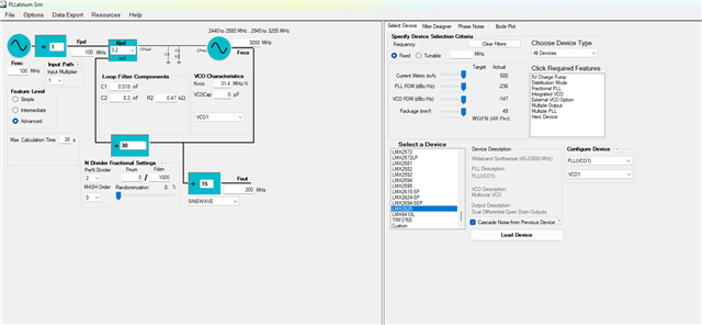
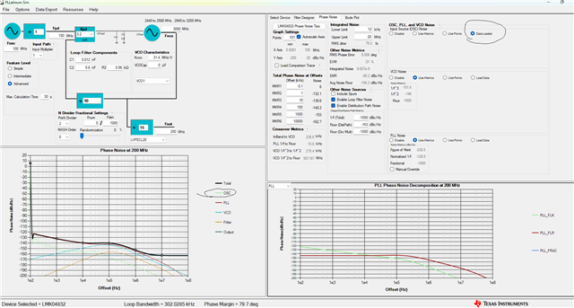
The master clock feeds the LMK which generates the SYSREF, 125 MHz for the JESD IP and a 200 MHz to the LMX.

Both chips are using internal VCO.

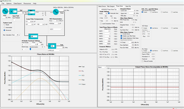
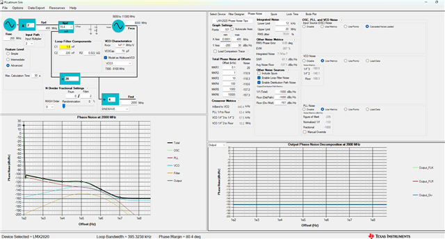
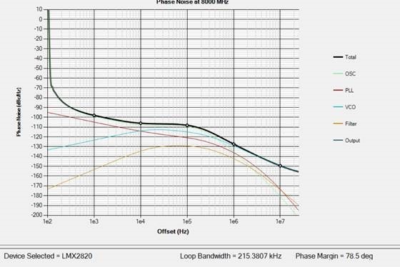
Now, we are not happy with the ADC's SNR and we have started looking into the clock, which we think could have too much jitter and possible too low level (It's only about 3.9dBm after BPF). The max output from the LMXs RFOUT is 6 dBm.

1, So, we placed the LMK in distribution mode with a 1G from a SMB100 generator. It seems that the clocks are OK, but while the DAC works but we loose sync on the ADC.

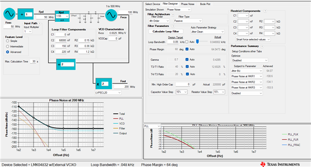
2, Then we changed the loop filter on the LMX only, tuning for jitter, (reverting back to original clock design)  and the same thing happened. DAC is still running.

We cannot easily access the clock but we are designing a couple of pcbs that we can install in-circuit and we have acquired a scope fast enough to have a look.

But can you think of anything that can cause the above? It's a properly designed board, and we have already fielded quite a few of these.

Cheers,

G

  • Hi G, 
    Please use PLLatinumSim to estimate Output PN performance for these devices with their respective loop filter. 
    If you have a text file of the PN for the 100MHz OCXO you can estimate output PN performance and cascade these devices. 

    Ill give you can example. 
    Here is the output PN for a noiseless 100MHz clock fed into LMK04832 with a 3GHz internal VCO frequency divided down to generate the 200MHz output. 

    RMS jitter from 12kHz to 20MHz with this loop filter configuration is ~79fs


    We can cascade noise from the previous device which in this case is the 200MHz output from LMK04832 and load LMX2820 now and the 200MHz output from LMK04832 is now the reference clock for LMX2820. 

    Doing this results in the following: 

    We optimize the loop filter for the LMX2820 now and the jitter is ~70fs for a 200MHz input (from previous LMK04832 result that is now cascaded as Fosc) generating a 2GHz output.

    These are assuming a noiseless source. 


    What you can actually do with in the very first step for the LMK04832 is load the input source noise. 

    Now the LMK04832 is estimating the output PN with the ref clk you will be utilizing. 
    This is a more accurate depiction of what to actually expect from the output PN of the LMK04832. 
    You can then cascade the LMK04832 and load the LMX2820 which will use the 200MHz output from the LMK04832 as reference to the LMX2820 but now this will be a more accurate system depiction since you're including the input source noise for the LMK04832 which generates a 200MHz clock which is fed into LMX2820 to create the 2GHz clock. 

    Best regards, 

    Vicente 

  • Vicente,

    Thx I will follow your process. As a part of our test we are bypassing the LMK PLLs completely using a 1G clock from SMB100, which is pretty much as good as it gets. We will try to optimize the loop filters for this clk and see if the ADC behaves as expected. 

    It will take a couple of days before i get back to you.

    Cheers,

    G

  • Vicente,

    We have successfully managed to get the LMK running providing a clean 200 MHz for the LMX with low spurs and minimum drift.

    Based on your recommendation we redid the settings/filter based on the data from the external clock and the EXVCO. We'''ll have a look at it with a jitter tester and a multigig scope on monday.

    Now, the funny thing is that the LMX is loosing lock. This is repeatable, if we send the LMK PLL1 out of lock with a different reference frequency, lets say 60 instead of 50, the LMX locks and generates the 8G and the 4G. If we send set the frequency back to 50 it will loose lock. A reboot or a recal does not help.

    Seen that before?

    We are waiting for a couple of RF probes so we can probe the 8/4G directly, but it will take another week.

  • Hi Geir,

    Can you share the configurations (for both the LMK04832 and the LMX2820) you are using that lead to this locking issue?

    Thanks,

    Michael

  • Geir, 
    Also, please use a PNA to measure phase noise. 
    A scope is not optimal for this kind of measurements due to higher noise floor than compared to a 5052 or an FSWP. 
    Use the PNA or a spectrum analyzer to check the output frequency. 

    Best regards, 

    Vicente 

  • The setup is: An external OCXO (OH300 50Mhz) -> LMK04832 with CVHD950 VCO 100MHz and internal VCO for PLL2 3GHz divided to 200 MHz  -> LMX2820 internal VCO 8GHz


    Using PLLatinum the file LMK4830-PLL1.sim was produced with phase data from OCXO and external VCO. Using the “Cascade noise from previous device” was used to produce the PLL2 and LMX2820 files.


    It seems using different versions of PLLatinum gives inconsistent results and crashes. These files are made from version 1.6.9.0


    Sometimes the Phase noise window shows a jump from positive dbc/hz values to negative at lower offsets:

    The concern is if this affects the calculated jitter?

    I cannot find a way to attach the files?

  • Hi Geir, 

    Version 1.6.9.0 should be a reliable version of Pllatinum Sim. In the top left hand corner, there should be a File tab, and under File there should be the option to Save Design. If you do that and then drag that file into the E2E prompt, it will attach.

    Thanks,

    Michael

  • Didn't read that memo :-)

    Here they are.

    ClockSim.zip

  • Hi Geir,

    Are you able to take a PNA measurement at the input to the LMX2820, like Vicente suggested earlier? That would illuminate whether the locking issue is due to phase noise or a software issue.

    Thanks,

    Michael

  • I don't have a phase noise analyzer available but I do have a decent 26G spectrum and a 16G scope. What span and resolution would you like?

  • Hi Geir, 
    A spectrum analyzer works, the carrier should be very precise to ensure we are locked to the correct frequency. 

    You can use this to check the LMK04832 output which feeds into the LMX2820. 

    Frequency should be centered appropriately. 
    Can you share your schematic and configuration files, preferably a .tcs file, so we may review? 

    Best regards, 

    Vicente 

  • We working on several different loop filters, as we are getting different results using the PLLatinum sw.

    We will also bring in a FSW tomorrow, it's better than the FSQ for phase noise. Included is the design file for the LMK and the design for the LMK. Now, we do not use the external oscillator for PLL2, as the recommended part is impossible to source. So Clk1 is not in use.

    I'll send you phase noise plots and oscilloscope plots tomorrow. 

    Once we clear out the LMK we can start looking at the LMX.

    Orginal200MHzToLMX.tcs

  • So we used a FSVA3030 with low jitter reference in order to do these measurements

    System ref clock. Jitter 153 fs

    LMK 50 MHz. Jitter 169

    LMK 200 MHz. Jitter 196 (Same clock that feeds LMX)

    And finally LMX 4 GHz. Jitter 180

    Is it possible to achieve 50 fs with the LMX?

    In order to measure the 4G we removed the in circuit BP filter and soldered in a 1m coaxial cable. We attached a 4 dB attenuator cable.

    Interestingly, we had to use RBW of 2Hz in order to measure, if we went to 1 Hz the signal dropped 30 dB. 

    We measured 10,100,500,1000,2000 Hz

  • Folks,

    Any input is highly appreciated. 

    We either have to solve this or we have to backtrace to the previous design, which used a competitors chip.Problem is, we will then loose the 4G/8G which is why we went with this solution, as we will go down to 3G instead.

  • Hi Geir,

    We appreciate your patience. I will try to replicate your findings in lab this week with a PNA. I am a bit confused about where you are taking your measurements. Is the second measurement at the OSCin input? Or somewhere else? The phase noise measurement for the second measurement is about what I would expect for the total jitter contribution of the LMK04832. 

    Would you also be able to share your .tcs file for the LMX2820? I can try with a signal generator to see if I can get it to lock.

    Thanks,

    Michael

  • When we modified the loop filter i.a.w. the pllatinum recommendations the  circuit became unstable and the output looked like Sauron's helmet.

    We measured the jittter from the 50MHz reference OCXO to be about 1.4ps. Not far from listed.

    The culprit in our design is the LMK. Meanwhile i noticed the fine results you achieved in the ADC 20Gh ref design.

    May I ask which values you recommend using our setup? For the LMK?

  • Geir, 
    1.4ps for an OCXO seems very high. What is the OCXO PN? I can search up the DS. 

    If using a R&S FSWP, can you measure the jitter using the phase noise analyzer feature instead? 
    Can you upload your most up to date schematic? I would like to review the loop filter with the current components. 

    May I ask which values you recommend using our setup? For the LMK

    On the customer EVM? Schematic and BOM can be found here: LMK04832EVM User’s Guide (Rev. A)

    On the reference design I am not sure which one you're referring to, but nevertheless you would need to reach out to the team who made the reference design. 

    Best regards, 

    Vicente 

  • Hi Geir,

    I took a look over the TICS Pro configuration you sent, and it appears your device was not locking. 

    This may explain the behavior you were seeing. I have attached an updated configuration that set the PLL1 N Divider appropriately.

    Updated200MHztoLMX.tcs

    I also took a look at the PLLatinum Sim output for this new file. I calculated the PLL1 loop filter values for a loop bandwidth of 48Hz (in the optimal range for jitter cleaning).

    I did the same thing for PLL2 - this time calculating PLL2 loop filter values for a bandwidth of 300kHz.


    Please use the updated configuration file, and try using these loop filter values.

    Thanks,

    Michael

  • Hi,

    Quick update: using the EVM's with your recommendations for loop filters with lab power supplies we managed 70-80 fs, measured on a FSVA3030 with improved jitter option. We measure from 100Hz to 10MHz.Had to use ferrites on the PSU's and everything else in order to get below 150.

    But in circuit we are still at 3-400 fs, which starts to point at emi issues? We ordered in a LMK61E2, programmed it to 1G and set te LMK04832 in distribution mode. No improvement.

    OOO this week. Will update.

    Have also ordered in a SMA100B for reference.