LMX2492: Maximum Speed of Programming Interface

Part Number: LMX2492

Tool/software:

Hi,

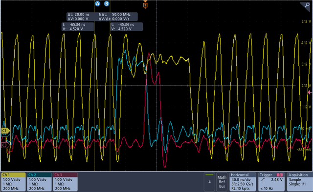
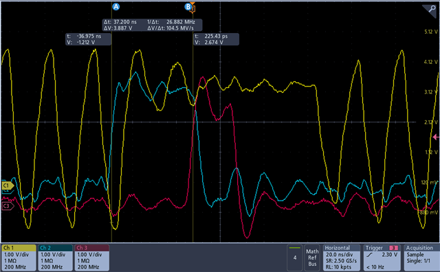
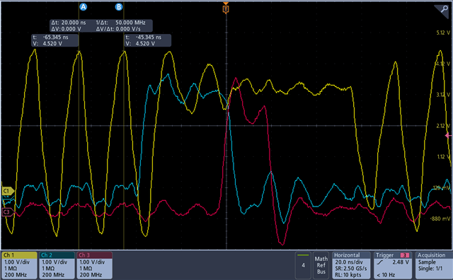
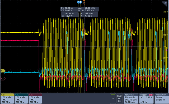
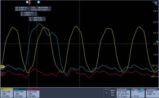
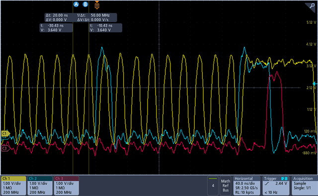
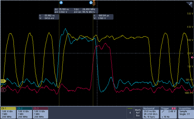
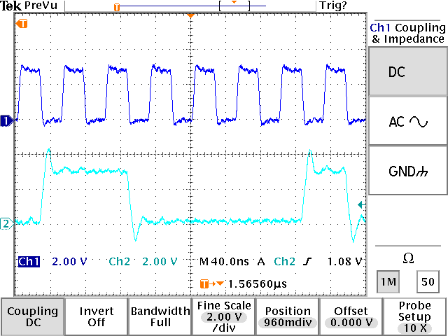
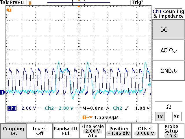
I try to reach maximum speed for programming interface CLK. It has 10 ns Clock Pulse Width High and 10 ns Clock Pulse Width Low. I understood that 20 ns CLK period. However I don't get above 20 MHz (50 ns). I worked it successfully for 20 MHz. Did you test programming interface speed?

If you tested for 20 ns, do you give any advices? I tried to check these things. Slew rate and timing diagram are proper for 50 MHz but it didn't work.

  • Hi There,

    Did you connect the SPI directly between the microcontroller and LMX device? Did you add any resistor and capacitor between them?

  • Hi,

    I added 22R series resistor each line. I didn't use capacitor. Do you share any schematics for these lines?

  • Hi There,

    Can you probe the SPI signals before and after the 22Ω resistor?

  • Yes, I can. Here the oscilloscope pictures.

    Here is the oscilloscope pictures for 22R before (MCU and 22R) .
    Yellow channel : CLK
    Blue channel : DATA
    Red channel : LE

    Here is the oscilloscope pictures after 22R (PLL IC and 22R)

    I tried to measure using cursors. I am using passive probe along measuring. 

    Also I didn't drive 25 MHz CLK: What is your advices?

    Thanks.

  • Hi There,

    At 20MHz, I expect I should see square wave signal.

    Please try again with higher SPI clock frequency.

  • Hi,

    I could not program the PLL for any value above 25 MHz. I tried 3 different spi master. Are you sure above 25 MHz CLK is proper for programming interface? I spent a lot of times for this. Are you sure that this pll is tested above 25 MHz?

  • Hi There,

    What is the SPI waveform before and after the 22Ω resistor?

  • Hi, 

    I shared measurings before for 50 MHz. I measured different speed. Waveforms don't change, they are almost like a sinus. I don't see any square wave for 20 MHz CLK or 25 MHz CLK. However I can program it. You are right for square wave if I try 100/200/500kHz or 1-2 MHz CLK speed. Also, I use passive probe and it applies low pass filter and square wave's edges can be less sharp. What exactly do you expect to see? 

    Here is what I tried: choosing slew rate is fast, trying different spi masters and taking measurements from different oscilloscope. 

    I think, waveforms are correct. Setup/hold, peak's voltage and slew rate is showned correct. 

  • Hi There,

    With 20MHz SPI clock, I expect to see square wave signal.

    Below is the plot with 20MHz SPI clock after 22Ω resistor.

    With 50MHz SPI clock, I can program the device to lock.

    Your plot at 20MHz is much worst than my 50MHz plot, you need to verify the signal at 25MHz or above. If the signal has very bad distortion, LMX2492 may not be able to decode the information correctly. 

  • Hi again,

    I use LMX2492 demo board. It is very interesting because if I don't tie GND between Ic and controller, IC is programmed 50 MHz. If I tie GND between them just one point, it has never programmed. I tried to tie different single point, the result is same it isn't programming. However I tie multiple points, IC is programmed. What is your advices? Isn't it programmed strange without connection between GNDs?

  • Hi There,

    Both GND should be connected together. Did you connect your controller to the TP on the board?

    if you connect the controller to the pins of the uWire, you should change the 10kΩ series resistors to something like 33Ω.