This thread has been locked.

If you have a related question, please click the "Ask a related question" button in the top right corner. The newly created question will be automatically linked to this question.

LMK5B33414: LMK5B33414EVM Zero Delay Mode 10Mhz has phase difference

Part Number: LMK5B33414

Tool/software:

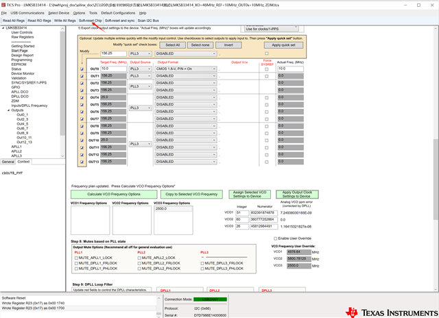
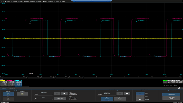
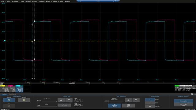
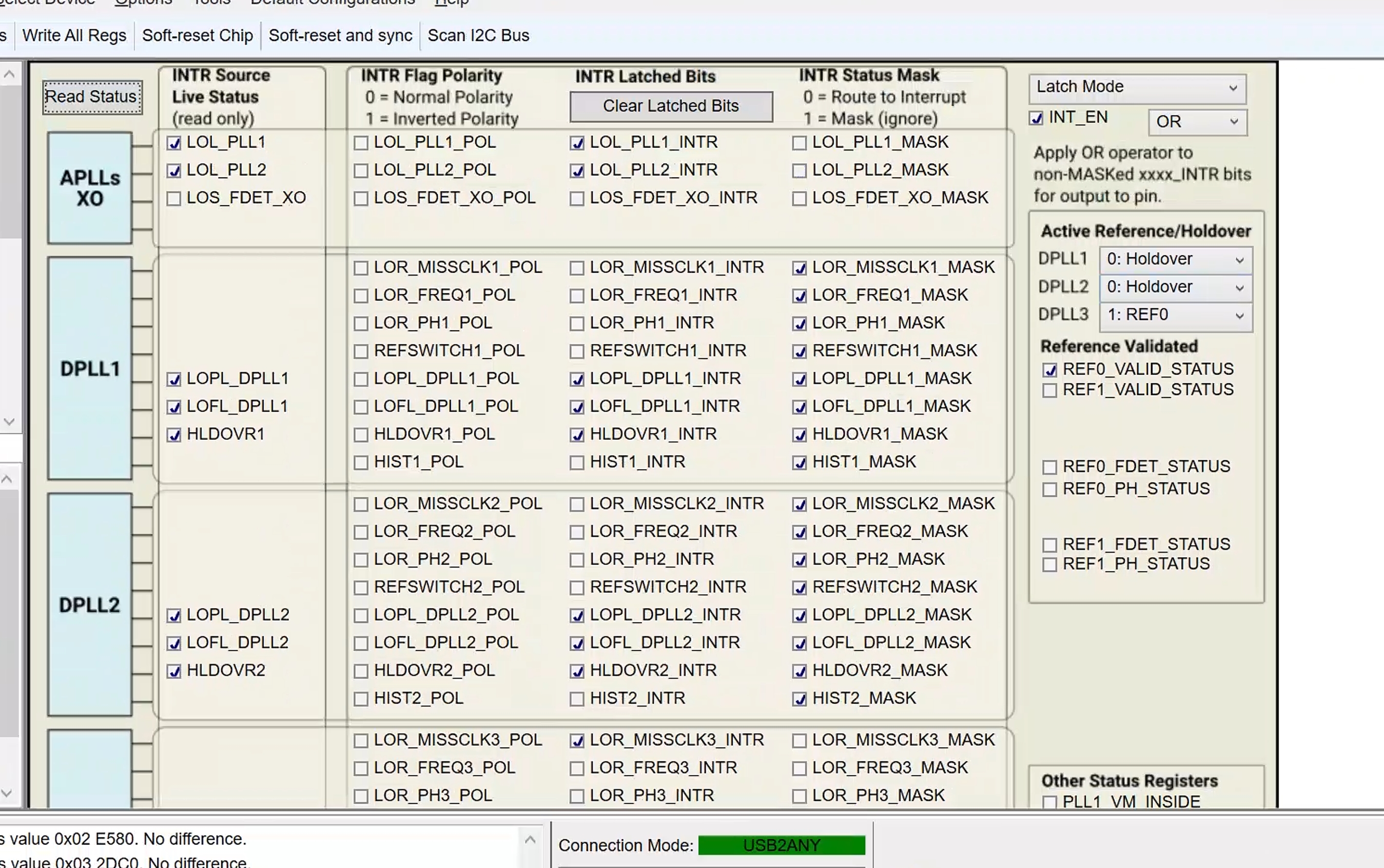
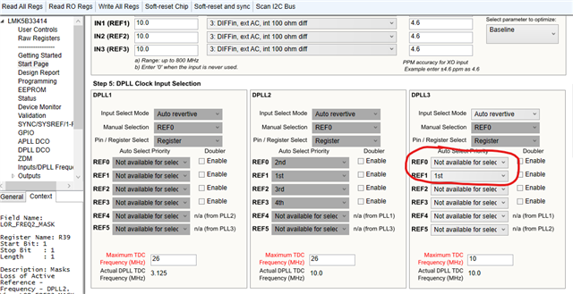
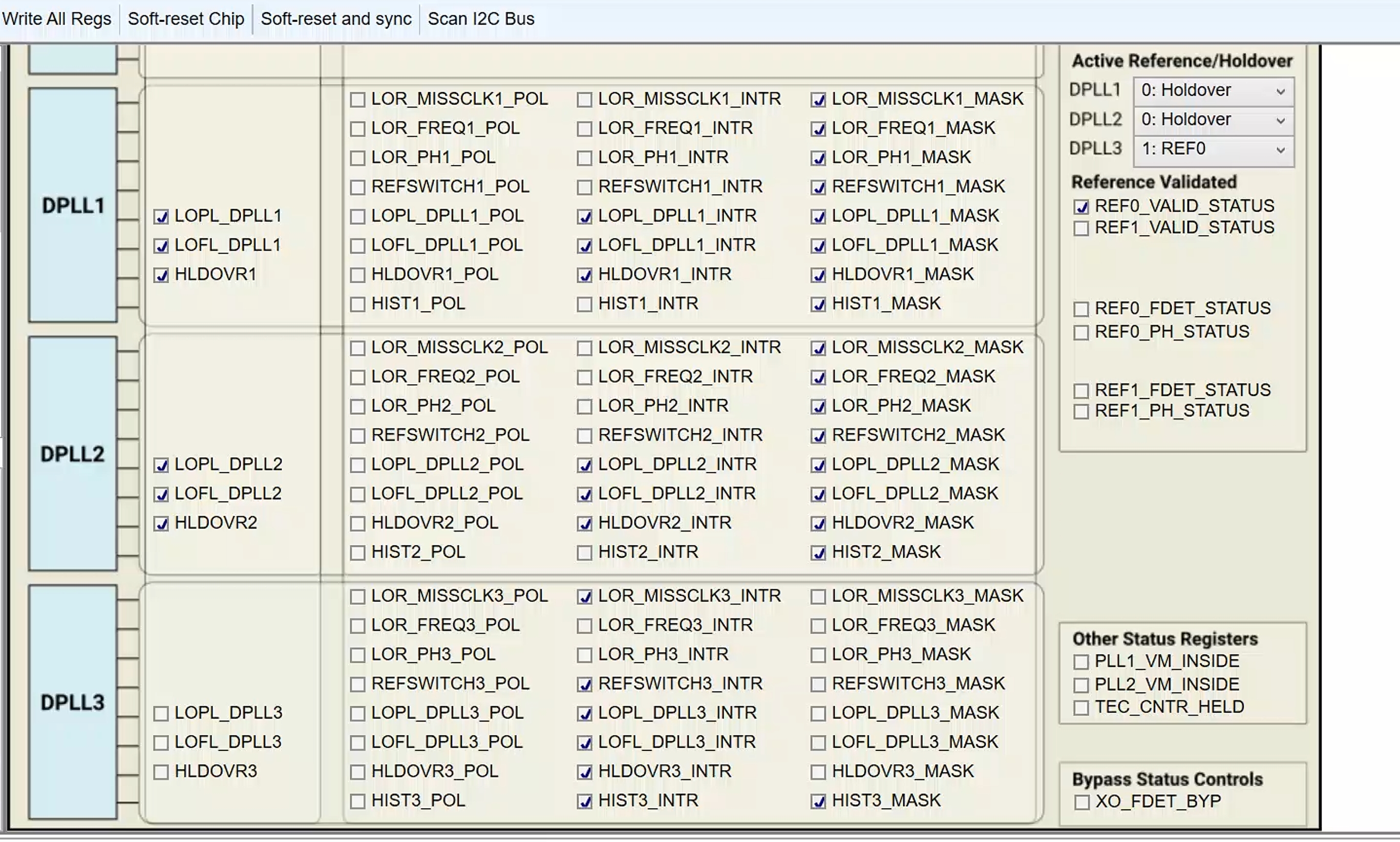
When I was testing the ZDM mode with a 10M reference input using LMK5B33414, I noticed that the phase of the reset chip was deviating. What could be the reason for this? The attachment contains my configuration file. The figure shows the phase difference between the output channel 0 of the software and the reference clock after several resets.

 LMK5B33414_10MHz_ZDM.rar

  • Hi Wenhao,

    Can you please share a screenshot of the Status page after programming and a reset? Make sure to click "Read Status".

    Regards,

    Jennifer

  • ...

    Thanks for your reply.The picture above shows the status of the status page.

  • Hi Wenhao,


    After loading your tcs file DPLL3 which uses ZDM is configured to only take a reference input from IN1. Pictured in the image of the GUI below.

    But on the status page image on the right side in the reference validation box we can see that only REF0_VALID_STATUS is checked. I changed the GUI to take both REF0 and REF1 as valid DPLL references. Can you try this new tcs configuration and report the new status page as well as if the part is working as expected.
    LMK5B33414_10MHz_ZDM DPLL3 REF0 valid.tcs

    Best Regards,
    Kyle Yamabe

  • Thanks for your reply.I've figured out the reason. It's because my reference clock was improperly set for AC coupling.But I have another question. When I use the single-ended direct current reference clock INO. The input signal is a 10M square wave signal with a 50-ohm impedance and a 2V amplitude.Occasionally, when the power is turned on, the lock will be lost and the read-out state will be as shown in my previous diagram.

  • Hello Wenhao,

    This seems to be because the status bits have not been updated or by the time the update occurs the device locks.

    The status page does not update unless the "Read Status" button is pressed. Immediately after power-cycling the board it will take time for the DPLLs to get phase and frequency lock. If you click the "Read Status" button during this period I would expect the  LOFL_DPLL3 and LOPL_DPLL3 = 1 for a short period of time. You can continue to click "Read Status" and should see the status bits clear.

    Best Regards,
    Kyle Yamabe