Tool/software:
Dear TI Team,
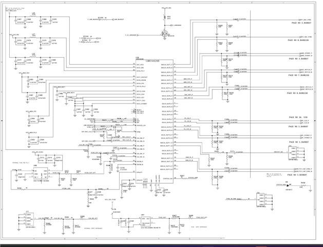
I am Pavan, and we are currently facing an issue with PLL locking on our custom board that incorporates the LMK04828B. We have developed a test application using a 19.54 MHz input on CLK_IN2. On our setup using the ZCU208 with the CLK104 module, the input gets locked successfully, and STATUS_LD2 indicates the output of the LMK is locked.
However, when running the same application on our custom board, the LMK does not lock, and both STATUS_LD1 and STATUS_LD2 remain low, indicating PLL1 and PLL2 are not locking.
Below are the design constraints and our observations:
-
We followed the same LMK04828B schematic as the CLK104 module. The original CLK104 uses a 160 MHz VCXO (15 PPM), which was not available. Hence, we replaced it with another 160 MHz VCXO with 50 PPM stability. All other schematic elements remain unchanged.
-
On our custom board, CPOUT1 generates 1.65 V as a control voltage for the VCXO. However, our VCXO requires 3.3 V control voltage to operate. To address this, we tested with an external level shifter to boost the voltage, but STATUS_LD1 and STATUS_LD2 still remain low — indicating that the PLLs are still not locking.
-
We suspect the issue may be due to the VCXO stability (50 PPM vs 15 PPM) and/or the control voltage requirements. The original CLK104 VCXO seems to accept 1.65 V directly. We also observed charging and discharging behavior on CPOUT1, indicating the PLL is attempting to tune the VCXO. To overcome the voltage incompatibility, we plan to use a comparator with a 1.65 V threshold to switch the VCXO.
-
We are considering replacing the VCXO with a lower PPM (e.g., <10 PPM) version of the same frequency to match the performance of the original CLK104 design.
We have also uploaded our custom schematic alongside the CLK104 LMK schematic for reference.
Kindly suggest appropriate solutions or recommendations to help resolve this issue.
Best regards,
Pavan