This thread has been locked.

If you have a related question, please click the "Ask a related question" button in the top right corner. The newly created question will be automatically linked to this question.

LMX2594EVM: Configuration Check

Part Number: LMX2594EVM
Other Parts Discussed in Thread: LMX2594,

Tool/software:

Dear TI Support Team,

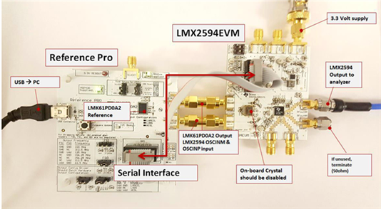
I am attempting to generate a 160 MHz differential output and a 10.24 GHz single-ended output using a Reference Pro board as the reference source and the LMX2594 evaluation board.

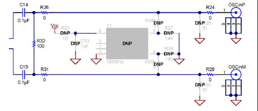
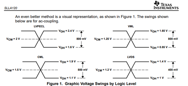
I configured the LMX2594 to accept a differential clock input and connected the boards together exactly as shown in the example connection diagram in the datasheet. The Reference Pro board circuit has not been modified. It is configured to output a 100 MHz clock with OS = 0, OE = 1, and LVPECL format.

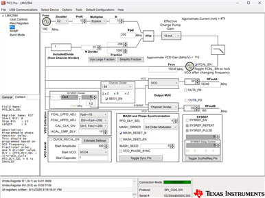
In TICS Pro, I selected the LMX2594, applied the configuration shown in the attached screenshot, and clicked “Write All” to program the registers. However, I am not observing any output from the LMX2594.

Could you please advise if there are any additional configuration steps, hardware settings, or initialization procedures required to obtain both the 160 MHz differential and 10.24 GHz single-ended outputs?

Thank you for your assistance

  • Hi Kim,

    Make sure the Reference PRO board is configured properly and you can measure 100MHz from the output.

    If you connect Ref PRO differentially to the LMX2594 EVM, modify the input of the EVM as shown below:

    Your TICS Pro configuration is fine.

  • Thank you for your guidance.

    I have already modified the EVM input as suggested and checked the circuit, and I can confirm that the Reference Pro board is outputting a 100 MHz differential signal correctly.

    I would also like to confirm:

    1. When I click "Write All" in TICS Pro, does that immediately apply the configuration to the LMX2594?


    2. There is a DIP switch on the LMX2594 EVM — are there any specific settings required for my configuration?

  • Hi Kim,

    Correct, Write All Registers or Ctrl+L will write all the registers once in descending order.

    The DIP switch is used to isolate the lock detect LED and MUXOUT output data. it is actually not necessary at all, you can keep them in the Make position.

    Were you not get any signal from LMX2594 or it is unlock?

  • It seems that the LMX2594 is neither locking nor giving any output. The screenshot I attached is what I get when I click Read Focused Register in TICS Pro. How can I properly check whether the device is locked or not?

  • On my LMX2594 board, all other bias pins show normal values, but VBIASVCO (pin 3) measures about 0.3 V, whereas the datasheet (Table 41) specifies about 1.3 V.

    At the same time, the device shows no lock and no RF output.

    Could you confirm if the low VBIASVCO (0.3 V), while other bias pins are normal, indicates an abnormal condition or device issue, and whether this explains why both lock and output are missing?

    For verifying lock status, is it correct to check either by reading the lock-detect register in TICS Pro or by observing the LD LED on the EVM? Could you please provide the recommended detailed method to confirm whether the device is properly locked?

    Thank you.

  • When I probe the C14/C15 node on the LMX2594EVM with an oscilloscope, I observe a 100 MHz waveform riding on an unexpectedly high DC level of about 3 V.
    This does not look normal to me. Is this expected behavior, or does it indicate an issue?

  • As a follow-up, I have attached an oscilloscope screenshot of the C14/C15 measurement, along with a reference diagram of typical differential signaling voltage swings.

    Given that the observed DC bias is around 3 V, which seems higher than the common-mode levels shown in the reference standards, could you please clarify whether this behavior is expected for the LMX2594EVM input?

  • Hi Kim,

    After Vcc power up without programming, I measured

    pin3 = 0.27V

    pin OSCinP = OSCinM = 1.58V

    After programming,

    pin 3 = 1.18V

    pin OSCinP = OSCinM = 1.56V

    After Vcc power up, what is the current drawn? My board is 146mA. After programming POWERDOWN=1, current drops to 4mA.

    Did you get similar data?

  • Whether I click Write All or not, pin 3 still measures around 0.28 V, and the supply current is about 10 mA.

    Another strange point is that the CSB_TP pin remains low all the time. When I checked for a short, the resistance measured 1.12 Ω, and it even beeps as if there is a short.

    It seems there is an issue. Since the chip select signal does not transition from high to low and stays low, I believe the device might not be writable from the very beginning.

  • Hi Kim,

    If you believe the EVM came faulty, you can request for a replacement. Contact our Customer Support Center (www.ti.com/.../customer-support.html).