LMX2582: Oerating conditions in output dividers

Part Number: LMX2582

Tool/software:

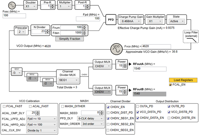
Some of LMX2582 devices do not divide correctly 7011.2MHz VCO, under the settings of CHDIV_SEG1: divide-by2, CHDIV_SEG2: divide-by8, CHDIV_SEG3: - (REG35: 0x109B, REG36: 0x0420). Others devices divide correctly.
In both cases, lock detectors indicate 'Locked', so output diviers seem not work correctly in some devices.

When I change the divider settings to CHDIV_SEG1: divide-by2, CHDIV_SEG2: divide-by4, CHDIV_SEG3: divide-by2 (REG35: 0x059B, REG36: 0x0441), devices work correctly.
At VCO frequency of 6627.2MHz, 6819MHz diveices work correctly.

Are these defective or does  
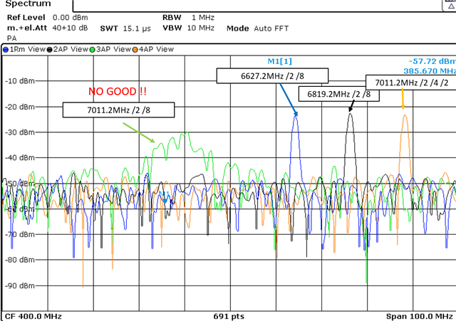
the divider have operating conditions?

  • Hi Ashida-san,

    If you need 4xx MHz, you should use a lower VCO frequency. Datasheet has the following:

  • Dear Fung,
    Thank you for your comment.
    Does VCO FREQUENCY in table 7-4 show the restrictions on the maximum VCO frequency?
    If so, in 2020 (before datasheet revision E is not issued..), using SEG1=2, SEG2=2 for 1414MHz output is accepted.
    e2e.ti.com/.../
    Is this use case not acceptable now?

  • Dear Fung,
    The Table7-4 suggests the setting of SEG1=3, SEG2=1, SEG3=1, in case of 1540MHz output.
    I tried with 2 settngs.
    Dividers do not work correctly with setting of SEG1=3, SEG2=1, SEG3=1 and VCO=4620MHz, but dividers work correctly with setting of SEG1=2, SEG2=2, SEG3=1 and VCO=6160MHz.
    The former setting is within the range of the table7-4, and the latter setting is outside of the range.
    What shoul I refer to ??

  • Hi Ashida-san,

    My board works with both configurations.

    With SEG1=3, SEG2=1, SEG3=1 and VCO = 4620MHz, are you not getting output in all devices or only in the same devices that you have reported having issues?

    FYI, below is the register setting in my setup.

    R70	0x460000
    R69	0x450000
    R68	0x440089
    R64	0x400077
    R62	0x3E0000
    R61	0x3D0001
    R59	0x3B0000
    R48	0x3003FC
    R47	0x2F00CF
    R46	0x2E0FA3
    R45	0x2D0064
    R44	0x2C0000
    R43	0x2B0000
    R42	0x2A0000
    R41	0x2903E8
    R40	0x280000
    R39	0x278204
    R38	0x26002E
    R37	0x254000
    R36	0x240411
    R35	0x23021F
    R34	0x22C3EA
    R33	0x212A0A
    R32	0x20210A
    R31	0x1F0601
    R30	0x1E0034
    R29	0x1D0084
    R28	0x1C2924
    R25	0x190000
    R24	0x180509
    R23	0x178842
    R22	0x162300
    R20	0x14012C
    R19	0x130965
    R14	0x0E018C
    R13	0x0D4000
    R12	0x0C7001
    R11	0x0B0018
    R10	0x0A10D8
    R9	0x090302
    R8	0x081084
    R7	0x0728B2
    R4	0x041943
    R2	0x020500
    R1	0x010808
    R0	0x00221C
    

  • Dear Fung,
    I am sorry for my miss judgement. My boards work with both configurations. The problem is in the following circuit.

    The output of LMX2582 drives a quadrature generator with a divide-by-2 method. I need  180-15400MHz output from divide-by-2/4/8. A divide-by3 output causes a large quadrature phase error in the following circuit.
    Are cofigurations such as SEG1=2, SEG2=2 and 1184-1540MHz of output frequecy available?
    e2e.ti.com/.../

  • Hi Ashida-san,

    So your problem is your system is not happy with odd divider output, this makes sense. 

    If your required frequencies are between 1184MHz and 1540MHz, I think it is fine to use SEG1=SEG2=2 to get divide by 4. 

  • Dear Fung,

    Of course, I want to use SEG1=SEG2=2 for over 1184MHz. But you mention about the restrictions of the maximum VCO frequency for each divider, and output frequency over 1184MHz with SEG1=SEG2=2 is outside of the range of Table7-4. Is this configuration is acceptable ??

  • Hi Ashida-san,

    The max. input frequency to SEG2 is approx. 3.3GHz. So SEG1=SEG2=2 is a valid configuration, as long as the output frequency is limited to 1540MHz.

    In general, we recommend follow Table 7-4, this would return predictable result. 

  • Dear Fung,

    Thank you for information about the max. input frequency to SEG2 . I use SEG1=SEG2=2 configuration. for 1184-1540MHz without worry.

    Regards.