Other Parts Discussed in Thread: LSF0102-Q1, TXS0102, TCA9509
Tool/software:
Hi TI team,
We are using TXS0102-Q1 in our SSD drive and the SSD module has been mass-produced. Now we are encountered a one-shot triggered question.
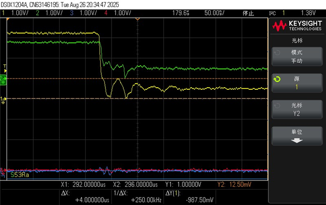
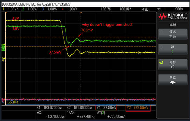
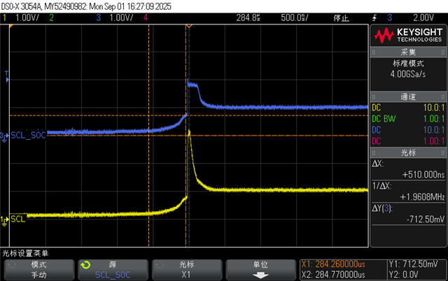
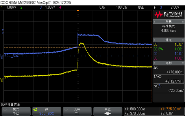
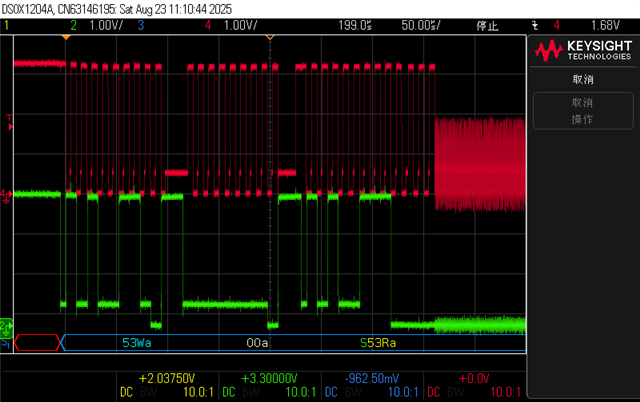
Q1: As the fail waveforms show below, we can see the TXS0102-Q1 trigger the one-shot on/off and the clk begins to vibration.
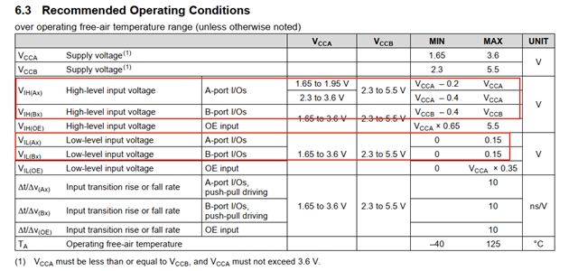
note1: Host output low voltage level is about 540mV.
note2: Soc stretch feature can Drive the clk to 0V from 540mV (It means that the low level can be drived to 0V when soc enable stretch feature); when soc does not drive(disable stretch feature) clk, the clk will rise from
0V to about 540mV. At this movement, we meet TXS0102-Q1 unexpected trigger one-shot then clk begins to vibration.
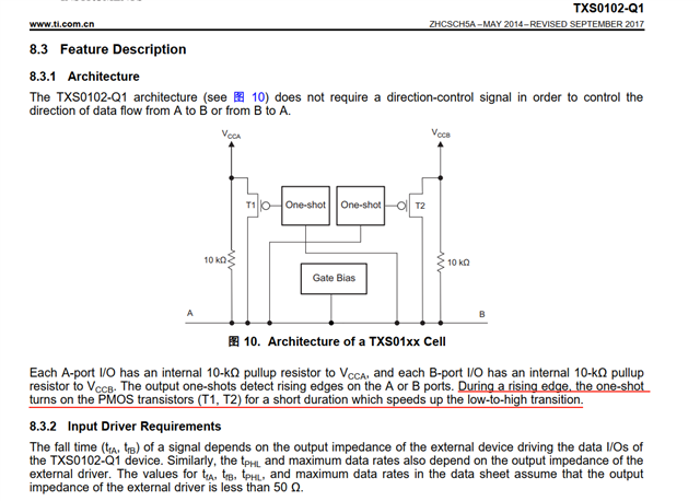
We would like to know what the triggering condition for "one shot" is.
waveform test point:
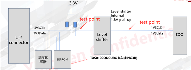
Fail waveform-1: CH4-3.3V clk, CH2-3.3V data;
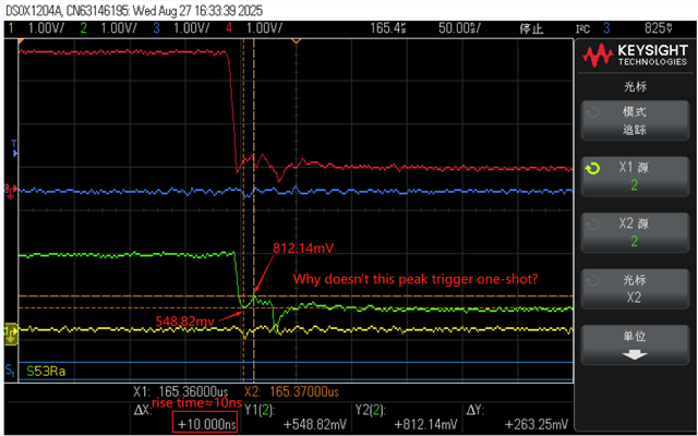
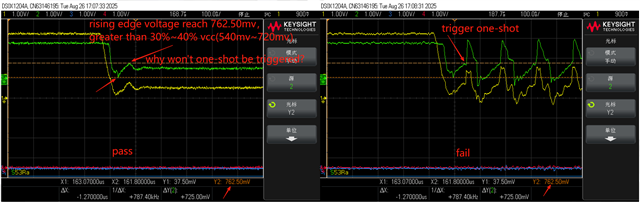
Fail waveform: SCL1 3.3V port, SOC_SCL 1.8V port

Fail waveform zoom in: SCL1 3.3V port, SOC_SCL 1.8V port

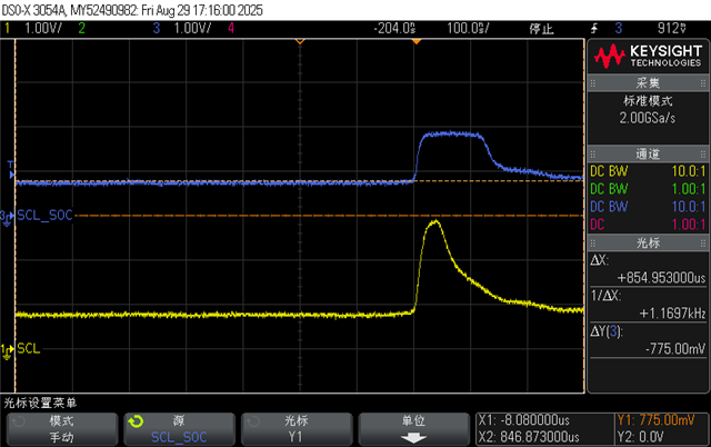
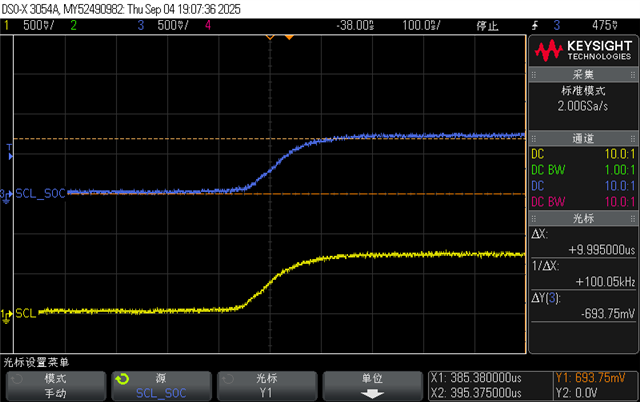
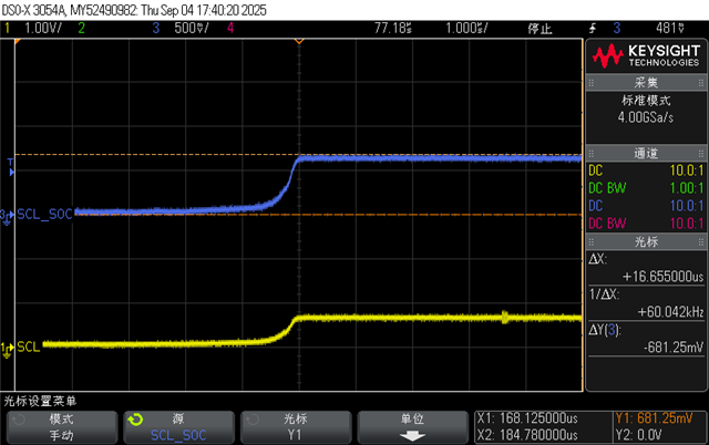
Q2: Why doesn't the under shoot trigger the one-shot mechanism? As I can see the ring peak voltage reach 1V and the one-shot mechanism does not trigger.
We would like to know what the triggering condition for "one shot" is.
under shoot waveform: CH1=3.3V port clk,CH2=1.8V port clk.