


Other Parts Discussed in Thread: LMK5B12212,
Tool/software:
To evaluate the jitter performance of the lmk5b12212 chip, the official evaluation board LMK5B12212EVM was used for testing. According to the instructions in the evaluation board manual, the on-board jumper cap and thin code switch were connected, and a 12V linear power supply and USB interface were connected. The FSWP signal source analyzer was used to test the phase noise and calculate the jitter value.
Use the official TICS PRO upper computer configuration to input the XO frequency, input the reference frequency (the reference is a 10MHz low phase noise temperature-controlled crystal oscillator input at the IN0P port), turn on a single differential channel output, and use Balun to convert to a single-ended signal for instrument testing, while turning off the outputs of other channels.
The expected test result is the test value given in the evaluation board manual: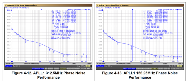
For details, please refer to page 33 of the evaluation board manual.
The jitter indicators in the chip and evaluation board are as follows: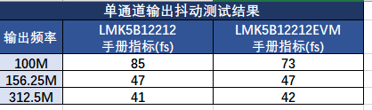
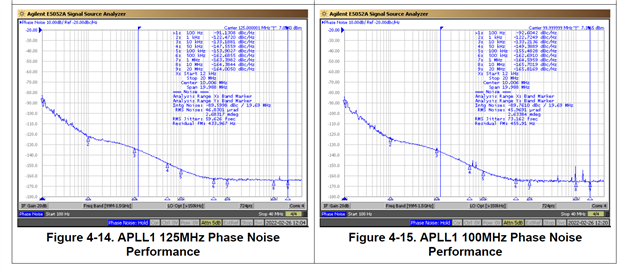
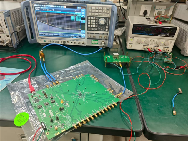
Next, the jitter performance will be tested using the evaluation board. The following are the real photos taken during the test: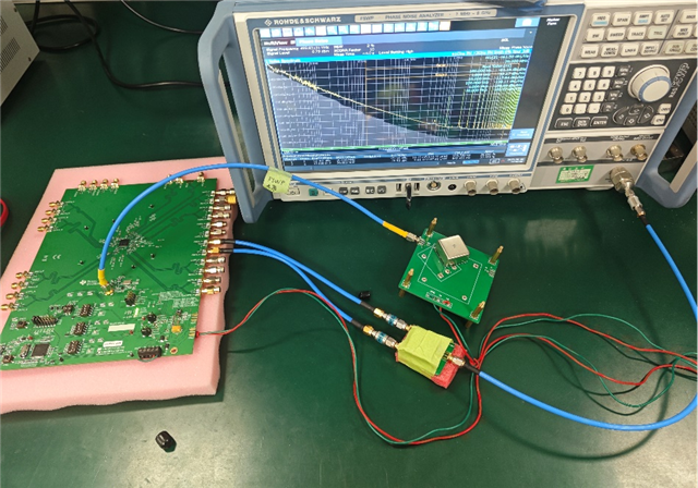
Tests have found that if DPLL+APLL1 is turned on, the output jitter is very poor: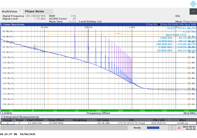
If DPLL is turned off and APLL1 is locked on XO, the jitter performance will be better.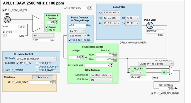
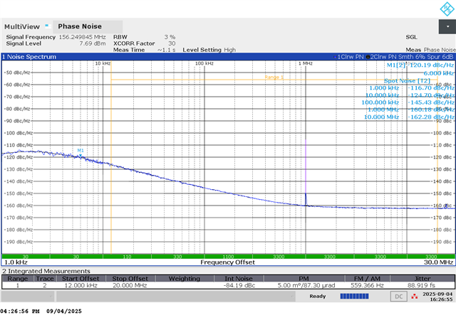
Furthermore, if the reference input of APLL1 is set to reserved and the BAW VCO runs freely, the jitter characteristics are the best at this time: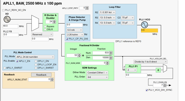
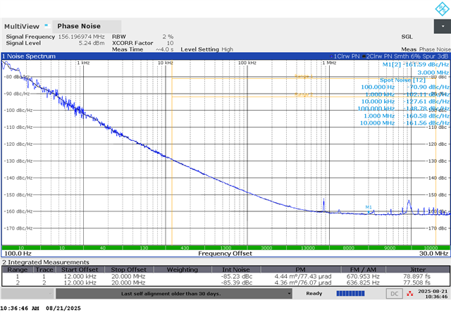
But it is still far from the indicators in the manual.
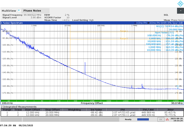
Subsequently, tests were conducted at 100MHz and 312.5MHz, but the jitter performance was still insufficient.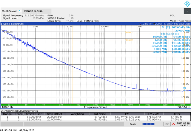
In addition, when the power supply mode of the evaluation board was changed to LDO power supply, it was found that the jitter performance was not optimized.
We also tried to use an external low-phase noise clock as the XO input to replace the on-board 48MHz crystal oscillator, but found that the test results did not improve.
Attempts were made to adjust the output frequency division coefficient and channel frequency division coefficient of APLL1, but the jitter performance failed to meet the manual indicators.
Summary: Through actual measurement, it was found that the jitter index given in the manual should refer to the index of BAW VCO, while the jitter performance obtained from the test using the evaluation board does not meet the index given in the manual.
Please help confirm the reason. Thank you
