


Tool/software:
Good afternoon,
We are using the LMX2595 to generate a 13.75 GHz tone. For this, we use a 25 MHz reference (we cannot change it, as the system design requires it to be 25 MHz). The problem is that when we measure the phase noise, we observe spurs between 10–40 kHz (marked in red) that we have not been able to eliminate.
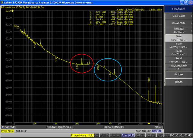
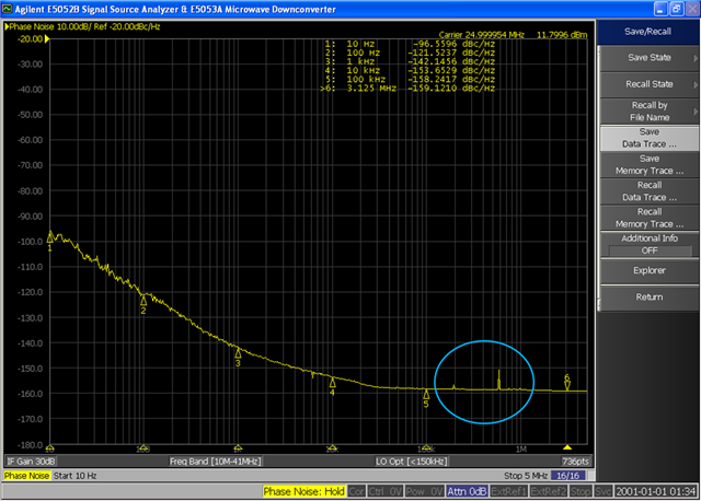
The spurs I marked in blue (200 and 600 kHz) seem to come from the 25 MHz signal we are using as a reference. I am also attaching the phase noise measurement of the reference.
We are programming the LMX2595 using Arduino, and these are the registers we are modifying:
Reg[78] = 0x0003 ;
   Reg[77] = 0x0000 ;
   Reg[76] = 0x000C ;
   Reg[75] = 0x0800 ;
   Reg[74] = 0x0000 ;
   Reg[73] = 0x003F ;
   Reg[72] = 0x0001 ;
   Reg[71] = 0x0081 ;
   Reg[70] = 0xC350 ;
   Reg[69] = 0x0000 ;
   Reg[68] = 0x03E8 ;
   Reg[67] = 0x0000 ;
   Reg[66] = 0x01F4 ;
   Reg[65] = 0x0000 ;
   Reg[64] = 0x1388 ;
   Reg[63] = 0x0000 ;
   Reg[62] = 0x0322 ;
   Reg[61] = 0x00A8 ;
   Reg[60] = 0x0000 ;
   Reg[59] = 0x0001 ;
   Reg[58] = 0x9001 ;
   Reg[57] = 0x0020 ;
   Reg[56] = 0x0000 ;
   Reg[55] = 0x0000 ;
   Reg[54] = 0x0000 ;
   Reg[53] = 0x0000 ;
   Reg[52] = 0x0820 ;
   Reg[51] = 0x0080 ;
   Reg[50] = 0x0000 ;
   Reg[49] = 0x4180 ;
   Reg[48] = 0x0300 ;
   Reg[47] = 0x0300 ;
   Reg[46] = 0x07FC ;
   Reg[45] = 0xC8DF ;
   Reg[44] = 0x05A3 ; // OUTA_PWR: 31 1FA3, 5 05A3, 0 00A3
   Reg[43] = 0x0000 ;
   Reg[42] = 0x0000 ;
   Reg[41] = 0x0000 ;
   Reg[40] = 0x0000 ;
   Reg[39] = 0x03E8 ;
   Reg[38] = 0x0000 ;
   Reg[37] = 0x0404 ;
   Reg[36] = 0x0113 ; //
   Reg[35] = 0x0004 ;
   Reg[34] = 0x0000 ;
   Reg[33] = 0x1E21 ;
   Reg[32] = 0x0393 ;
   Reg[31] = 0x43EC ;
   Reg[30] = 0x318C ;
   Reg[29] = 0x318C ;
   Reg[28] = 0x0488 ;
   Reg[27] = 0x0002 ;
   Reg[26] = 0x0DB0 ;
   Reg[25] = 0x0C2B ;
   Reg[24] = 0x071A ;
   Reg[23] = 0x007C ;
   Reg[22] = 0x0001 ;
   Reg[21] = 0x0401 ;
   Reg[20] = 0xE048 ;
   Reg[19] = 0x27B7 ;
   Reg[18] = 0x0064 ;
   Reg[17] = 0x012C ;
   Reg[16] = 0x0080 ;
   Reg[15] = 0x064F ;
   Reg[14] = 0x1E70 ; //15mA 1E70, 6mA 0x1E10, 9mA 0x1E50, 12mA 0x1E30
   Reg[13] = 0x4000 ;
   Reg[12] = 0x5001 ;
   Reg[11] = 0x0018 ; //
   Reg[10] = 0x10D8 ;
   Reg[9] = 0x1604 ;
   Reg[8] = 0x2000 ;
   Reg[7] = 0x40B2 ;
   Reg[6] = 0xC802 ;
   Reg[5] = 0x00C8 ;
   Reg[4] = 0x0A43 ;
   Reg[3] = 0x0642 ;
   Reg[2] = 0x0500 ;
   Reg[1] = 0x0808 ;
   Reg[0] = 0x241C ;


// Poner RESET = 1 (set)
uint16_t r0 = Reg[0];
LMX2595.writeMessage(SS_PIN, 0x00, (uint16_t)(r0 | 0x02)); // R0[1] = 1
delay(1); // pequeña espera para que el cambio se capture

// Poner RESET = 0 (clear) — usa AND con la máscara invertida
r0 = Reg[0];
LMX2595.writeMessage(SS_PIN, 0x00, (uint16_t)(r0 & (~0x02))); // R0[1] = 0
delay(1);

// 4. Program registers as shown in the register map in REVERSE order:
     for (int i =78; i>=0; i--){
      LMX2595.writeMessage(SS_PIN, i, Reg[i]);
     }

delay(10); // paso 5: esperar 10 ms (datasheet)
r0 = Reg[0];
LMX2595.writeMessage(SS_PIN, 0x00, (uint16_t)(r0 | 0x08)); // R0[3] = 1 (FCAL_EN)
We are not using any DC-DC converter or LDO to power the LMX2595. Do you know how these spurs could be generated?
Thanks in advance.
Gabriel.
