LMX2594: Regarding output power with EVM

Part Number: LMX2594

Tool/software:

Hi support team all.

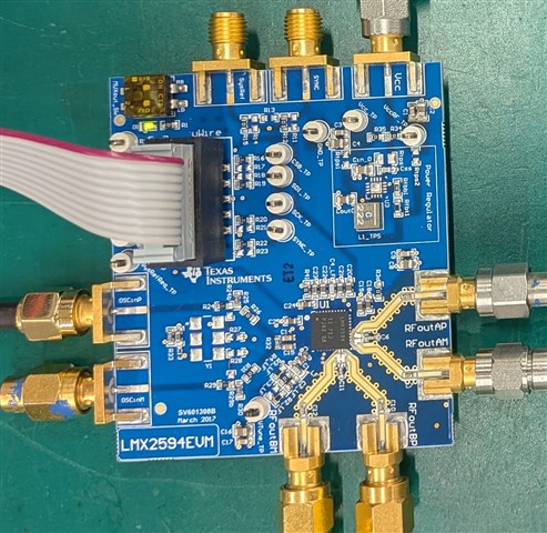
My customer is testing with LMX2594EVM.
Currently, Vco=14.4375 GHz, single end output of RF_AP only is -2dBm. (RF_AM is 50 ohm terminated.)
As there is no data available, could you please answer the following questions?

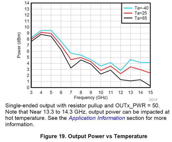
Regarding the output power graph (Fig19) in the data sheet of LMX2594, is this data obtained by EVM?
Also, is this the result of differential measurement?
-> If yes, is it correct to assume that it is about -3dbm at 14 GHz when measured at a single speed?
(Ta=25degC.)

Details of the data obtained by EVM are as follows.

Out Freq.[GHz]

OUTx_PWR=50

OUTx_PWR=31

OUTx_PWR=15

3.35

8.57

8.36

4.66

3.61

8.3

8

4.8

13.4

-0.16

-0.2

-2.2

14.44

-2.2

-2.1

-3.15

Best regards,

DH

  • Hi Higa-san,

    All power measurement is single-ended.

    Are you using a coaxal cable to connect the EVM and test equipment? I recommend use a SMA male-to-male connector instead of cable. 

    The data in the plot is a typical data, it is normal that we may see variation over parts. 

  • Hi Fung-san

    Thank you for your reply.

    I understand that you are measuring with single ended.
    The result is -2dBm compared to 2dBm, so the output power seems to be quite low.
    As for the connection, SMA connector and coaxial cable are used as shown in the attached picture.
    I also attach the configuration file.

    What else could be the cause of the low output power?

    Vco14.4375GHzFpd25MHz.tcs

    Best regards,

    DH

  • Hi Higa-san,

    My board is measured -0.2dBm on RFoutA, -1.7dBm on RFoutB. If you need higher output power at 14GHz, use RFoutA. 

    There is nothing we can do in the configuration to increase the output power. We have to do it in pcb layout. For example, use coplannar waveguide for the RF traces, use low loss pcb material and use shorter trace. I have another board with very short trace, I can get 2dBm at 14GHz. 

  • Hi Fung-san

    Thank you for your kind support.

    I understood well.

    Best regards,

    DH

  • HI Fung-san

    I apologize for asking this after we closed the discussion, but could you please answer one last question? Does your measurement value include the cable insertion loss, or is it a corrected value (excluding the cable insertion loss)?

    Regards,

    DH

  • Hi Higa-san,

    I did not use cable. 

    On the test equipment, I used a N-to-SMA (male) adapter, EVM was connected to the adapter directly.

  • Hi Fung-san

    May I ask one more question? From what I understand about your measurement setup, your readings appear to be taken at the output terminal.

    However, I don't understand why REFout_B shows worse performance. Is there any information that could shed light on the reason for this?

    Or perhaps you could share your perspective on this?

    Best regards,

    DH

  • Hi Higa-san,

    The unbalance between A and B is probably due to pcb layout and the external 50Ω pull up. At 14GHz, pcb layout as well as soldering becomes important. The position of the external 50Ω pull up will affect the output power. The amount of solder (for the pull up resistor) on the trace will also affect the impedance of the trace. 

  • Hi Fung-san

    I don't understand why there is a 2dBm difference between my measurement results and yours in an equivalent measurement environment.
    My last question is that I think the revision of the EVM used for the measurement is different. Have there been any changes to the layout or materials between the EVM revisions?

    Best regards,

    DH

  • Hi Higa-san,

    There is no change to the pcb layout and material. 

    Measurement at 14GHz requires very good test facility. 

    Test equipment, cable, connector, adapter have to be able to support 14GHz. 

    This device consumes over 400mA current, the power loss in the Vcc supply cable could matter. Make sure the voltage at Vcc_TP is 3.3V.