Other Parts Discussed in Thread: CDCE6214
Tool/software:
Hi Forum,
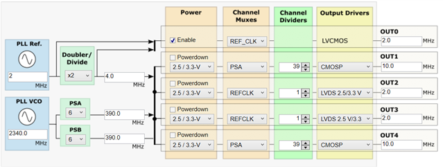
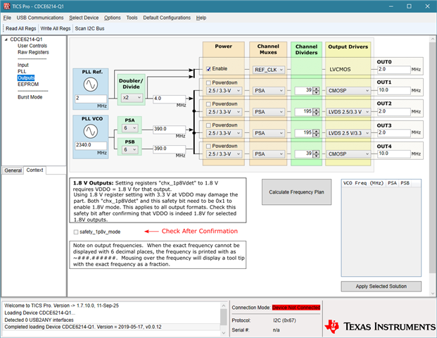
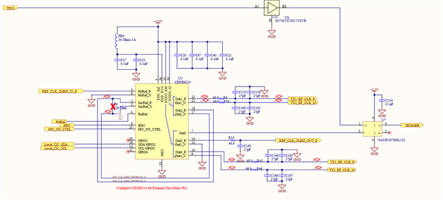
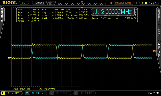
Above I have our current implementation of the clock IC. We are getting the correct output frequencies but the output is inverted or 180 degrees out of phase. We are using OUT3 to drive the next boards clock chip, Below is the Refrence clock (Yellow signal) from the first board and the OUT3 (blue signal) going to the pri reference input on the next board.
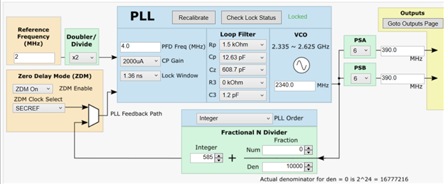
Zero delay mode is enabled and below is the register settings.
R85	0x00550000
R84	0x00540000
R83	0x0053FF00
R82	0x005205C0
R81	0x00510004
R80	0x00500000
R79	0x004F0008
R78	0x004E1000
R77	0x004D0000
R76	0x004C0188
R75	0x004B4008
R74	0x004AA181
R73	0x00490000
R72	0x00480027
R71	0x00470006
R70	0x00460808
R69	0x0045A181
R68	0x00440000
R67	0x0043C001
R66	0x00420006
R65	0x00410808
R64	0x0040A181
R63	0x003F0000
R62	0x003EC001
R61	0x003D0000
R60	0x003C0008
R59	0x003B2008
R58	0x003A502C
R57	0x00390000
R56	0x00380027
R55	0x0037001E
R54	0x00363400
R53	0x00350069
R52	0x00345000
R51	0x003340C0
R50	0x003201C0
R49	0x00310013
R48	0x00301A14
R47	0x002F0A50
R46	0x002E0000
R45	0x002D4F80
R44	0x002C0318
R43	0x002B0051
R42	0x002A0002
R41	0x00290000
R40	0x00280000
R39	0x00270000
R38	0x00260000
R37	0x00250000
R36	0x00240000
R35	0x002327F8
R34	0x00220000
R33	0x00212710
R32	0x00200000
R31	0x001F0000
R30	0x001E0249
R29	0x001D0000
R28	0x001C0000
R27	0x001B0005
R26	0x001A0000
R25	0x00193400
R24	0x00180719
R23	0x00170406
R22	0x001600A2
R21	0x00150585
R20	0x00140000
R19	0x00130000
R18	0x00120000
R17	0x001126C4
R16	0x0010921F
R15	0x000FA037
R14	0x000E0000
R13	0x000D0000
R12	0x000C7002
R11	0x000B0000
R10	0x000A0000
R9	0x00090000
R8	0x00080001
R7	0x00070C0F
R6	0x000619EC
R5	0x00050008
R4	0x00040000
R3	0x00030000
R2	0x00020003
R1	0x00012310
R0	0x00001500
we need to get the input 2 MHz signal input and the output to be in phase. Is there a way to do this?
Thank You,
George Vigelette