This thread has been locked.

If you have a related question, please click the "Ask a related question" button in the top right corner. The newly created question will be automatically linked to this question.

LMX2572EVM: Difficulty getting the board working

Part Number: LMX2572EVM
Other Parts Discussed in Thread: LMX2572, USB2ANY

Tool/software:

Hello, we are research team looking to use the sweep function on the LMX2752 chip for quantum applications. We want to use this chip in our publishable work however we are not getting the expected output.

We have tried various configurations and setups including:

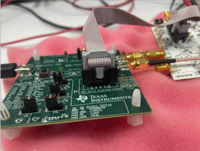
- Custom LMX2572 PCB with a microcontroller and SPI

- LMX2572 EVAL with TICS Pro

- Tics pro with custom LMX PCB


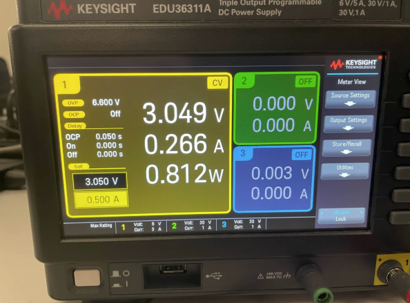
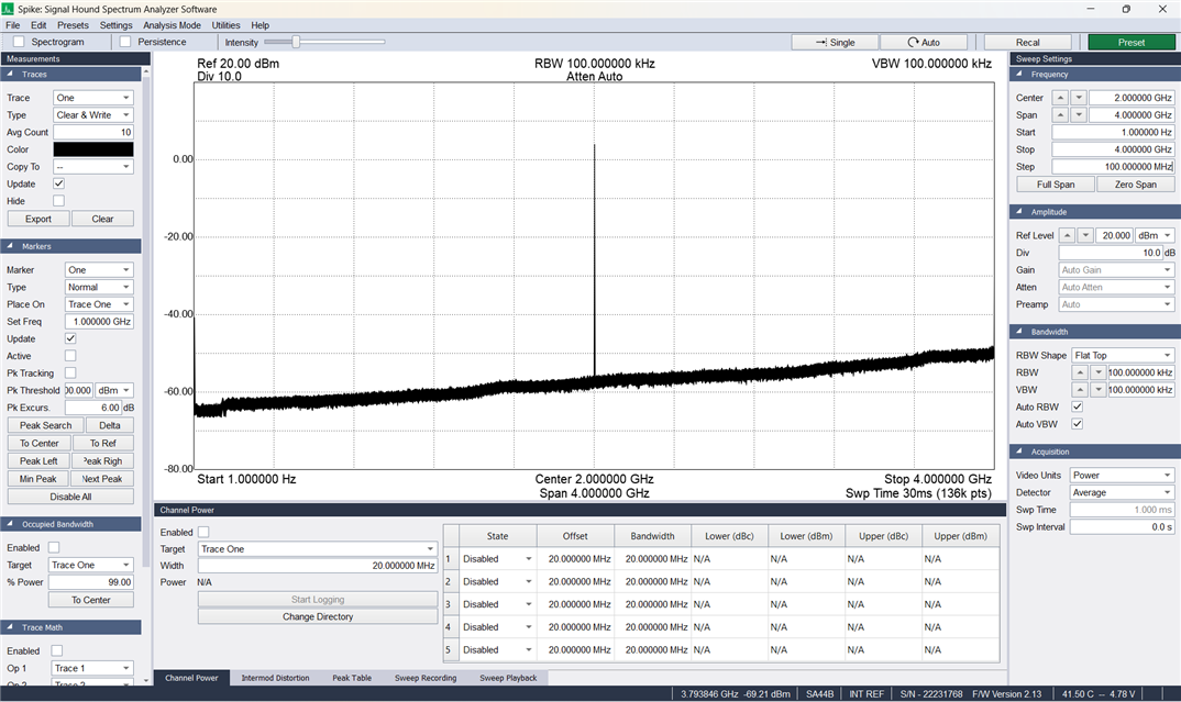
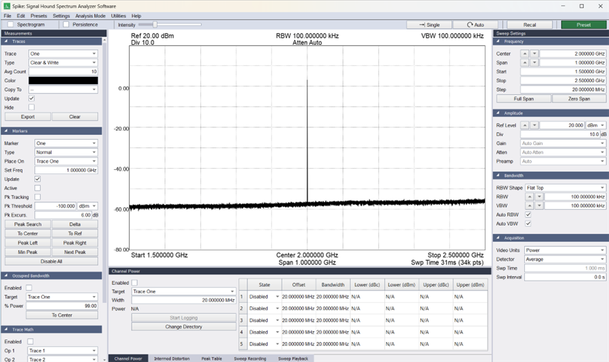
We are unable to generate the default 3GHz output, nor are we able to read back register values in any of the configurations. Additionally, we observe around 245mA of current draw, instead of the stated max 150mA on the EVAL board.

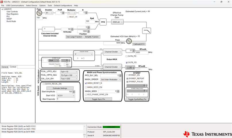
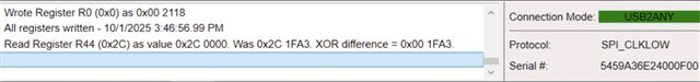
Using TICS Pro We used the default configuration of Default Mode 2018-4-24, set the MUXout_SW Switch 1 and Switch 2 to Make and Break respectively (Section 2.7 of datasheet), and set the MUXOUT_LD_SEL to Readback (Section 3.2.6). Then we set register 44 to a known value (0x1FA3), write all registers, and then used the "read back register" function. Please note that after writing all registers the current draw jumps from 245mA to 260mA.

Trying to read back a register yields only zeroes in this state.  (See image below). 


We developed our own PCB at first and encountered the same issues as before. Testing our own made PCB with the green devboard continued to yield the same problem of no frequency output and the inability to read back registers.

If you could provide any insight on how to read back registers or output the correct signal, it would be much appreciated. Please let us know if you need more information.

  • Hi Andrew,

    Over 200mA current is definitely not right.

    Could you follow section 7 of the user's guide (https://www.ti.com/lit/pdf/snau217) to debug? 

  • Hello, thank you for replying!

    I have followed the section 7's troubleshooting guide and found that the output frequency can be seen at 2GHz by default (rather than the standard 3GHz). Rewriting registers does not change the output frequency, and I am still unable to read back the register values. Below is a breakdown of our troubleshooting. Please let me know what next steps you would like me to try or what more info you would need. Thank you!

    Verify Hardware Setup:

    • Validate power supply is connected, turned on, and current limit is appropriate for device.
      • I tried at 3.05V and 3.3V and the outcome was the same.
      • At 3.3V
      • At 3.05V
    • Validate OSCin signal is supplied and turned on, if required.


    • Ensure programming cable is hooked up to the board.


    • Ensure spectrum analyzer center frequency matches target frequency. Choose wide span so that the carrier can be seen if it is off frequency.
      • 2GHz Signal
      • I also want to note that changing the output frequency does not change the 2GHz output

    • Ensure device is not powered down by the CE pin.
      • CE is at 2.75V


    • Load all registers (Ctrl+L)


    *Then Check Lock*


    • Revert to default mode in the software under "Default Configuration"
    • Validate that no boxes are red. If so, mouse over and read the tool tips.

    • Ensure that all the frequency boxes values are correct. Also understand that the VCO frequency could be different than the output frequency as there are often dividers after the boxes.
      • Output frequency is stuck 2 GHz no matter how registers are written.
    • Load all registers (Ctrl+L).
    • Try Readback at this point. If necessary.
      • MUXout settings shown above
      • The 2 switches were tried in all possible combinations
      • I am unable to readback a register. Having SW2 in either position seems to not affect anything.
      • Having SW1 in the make position reads back the following message
      • Having SW2 in the break position reads back as all zeroes

    *Then Check Lock*


    • Go to "USB Communications", "Interface", ensure that the USB2ANY button is turned green. Click "Identify" to have the program blink the green LED.
      • Verified
    • Send simple one way communication to the device such as: POWERDOWN, RESET, or change the status of a pin. Realize that if a RESET is done, do a Ctrl+L to refresh the registers afterwards. For POWERDOWN, you can validate this looking at the current on the power supply.
      • Reset box when checked turn off 2GHz sample. Ctrl+L does not turn the frequency back on, only unchecking the box brings the 2GHz signal back
      • Powerdown check box does not seem to do anything. 2GHz frequency and CE remain unchanged when the POWERDOWN box is checked


  • Hi Andrew,

    The POR current of the eval board is about 29mA. 

    POWERDOWN current is about 3mA. 

    With TICS Pro Default Mode configuration, operation current is about 94mA, output is 3GHz.

    Your current is too high. Can you measure the current again with the board hook up to just the power supply only? If you get much more than 30mA, I think your board has problem.

  • The current with the board hooked up to only the power supply yields 255mA. What would be the next steps to follow after this?

  • Hi Andrew,

    If you bought it from our distribution channel, contact them for a replacement.

    If you bought it directly from ti.com, please contact Customer Support Center (www.ti.com/.../customer-support.html) for a replacement.