


Part Number: NE555
Hi exparts,
Q1. We are considering 555 timer replacement (M51843P=>NE555). From previous schematic, RA=1.5korm, RB=1.5korm, C=0.01uF. Based on equation (4) in data sheet P12, f = 1.44 / {(1.5k + 2 × 1.5k) × 0.01u} = 32kHz. However, looking at the output results of past circuits using the M51843P, it was 16 kHz (RA, RB, and C are unchanged). Do you have any ideas about why this double frequency difference is occurring? Is there a mistake in the formula?
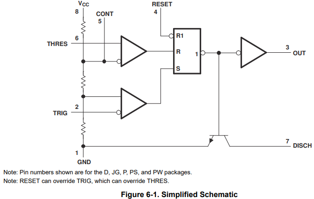
Q2. Does the Frequency Divider(6.3.3) work on the following principles?
- Once a high is input to S of RS-FF, 1 outputs low (out goes high) until a high is input to R.
- While OUT is high, C is charged until the voltage at C exceeds 2/3 x Vcc.
- During this period, even if a pulse is input to the TRIG pin, there is no change in the RS-FF output (it remains low), so the division function is realized by adjusting the time constant.
Q3. In order to drive a frequency divider, I think it is important to balance the time constant with the period of the input pulse to trig. Is there a formula that needs to be met to achieve this?
Regards,
Hiromu
