LMK1C1104A: 1.8V 1PPS signal (Input) to 3.3V 1PPS signal (1:4 fanout)

Part Number: LMK1C1104A
Other Parts Discussed in Thread: LMK00804B-Q1, CDCBT1001, LMK00804B

My requirement is to input a 1.8V 1PPS signal to LVCMOS Clock Buffer and 4x 3.3V 1PPS output.
LMK1C1104A was the recommended part by the customer support.
I just need to clarify some points.

This is the related question of 

Do you have any reference for AC coupling and rebiasing the input clk to LMK1C1104A or with any clock buffer with such a use case .Since as per datasheet the 
VIH = 0.7 * 3.3 = 2.31V
VIL = 0.3 * 3.3 = 0.99V  
@VDD =3.3V

and my input is 1.8V 1PPS signal

Will there be any slew rate or voltage shift issue? so that we need to take care something.
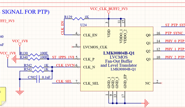
Is the bias resistor R1 and R2 100Ohm and AC coupling cap 0.1uF
Is this AC coupling and rebiasing configuration OK?
  • Hi, 

    AC-coupling is generally not recommended for 1pps signals because the AC-coupling caps will be charged/discharged on each edge of the input signal since the period is very slow, which can have some undesired transient behavior. See the waveform below as an example: 

    I would expect that this type of input waveform could be ok for LMK1CA, but I haven't personally tested this setup myself. Keep in mind that the switching threshold for LMK1C is set to VDD/2 (around 1.6V), so the duty cycle / pulse width of your input signal won't be preserved on the output. I would also set the DC bias to be a bit below the switching threshold to prevent the output from chattering in between edges, if you can set the common mode to something more like 0.3*VDD or 0.4*VDD and still meet the VIH/VIL requirements I think that would be preferred. 

    Is your 1.8V 1pps signal being sourced from an LVCMOS driver? If so, the 100 Ohm pullup/pulldown will behave as a 50 Ohm load and will reduce the input amplitude depending on the output impedance of your driver. I would recommend switching the pullup/pulldown to have a parallel impedance of >1k Ohm to keep the input amplitude as high as possible. Combining this with my point above, you could try something like R1 = 2500Ohm, R2 = 1500Ohm as a starting point. 

    Regards, 

    Connor 

  • OK then can you recommend any other buffer for this application?

    my first plan was to use LMK00804B-Q1 and input this 1V8 to it's CLK_P pin with below configuration:


    But then the recommendation from customer support was to use this LMK1C1104A 
    But if AC coupling and rebiasing may cause some initial shift of voltage in some cases
    at present I can't do experiments due to some time constraints so could you please recommend a suitable part for it?

  • One solution is to use CDCBT1001 as a 1.8V to 3.3V level translator for your 1pps signal since the operating frequency can go down to DC. You can then feed the output into LMK1CA for fanout. I believe this would be the preferred approach since your duty cycle / pulse width of the input 1pps will be preserved, and there shouldn't be any signal compatibility issues in terms of AC-coupling and re-biasing.

    Alternatively, if you want a one chip solution then you could try just using LMK1CA with the biasing scheme that I mentioned in my last reply. I expect that it would be functional, but it might require some experimentation with the R1 and R2 values for biasing to ensure the best performance. 

    I personally wouldn't recommend LMK00804B as a first choice since it hasn't been tested as extensively for 1pps signaling, but if you require an automotive-qualified device then it could also work for your application. You would need to update your biasing scheme to shift the common mode and make sure that VIH is at least 2V, which introduces some of the same problems that I mentioned above with LMK1CA. Let me know if you have any other questions. 

    Regards, 

    Connor 

  • We require the components to withstand -40 to 105C temp minimum.
    Since CDCBT1001 is an industrial grade component could you please suggest an alternative.

  • Hi Abhijith,

    It could be possible to AC couple with a considerably larger capacitance value, such that the 1PPS period is no longer large enough for the capacitor to discharge. 

    We will try some simulations and get back to you early next week.

    Thanks,

    Michael