This thread has been locked.

If you have a related question, please click the "Ask a related question" button in the top right corner. The newly created question will be automatically linked to this question.

CDCI6214: Y0 Clock @ 50MHz

Part Number: CDCI6214

Hi,

We use the CDCI6214RGE in one of our projects.
We use Y0 to output an LVCMOS clock.
We also use the Y2 and Y3 to generate LVDS clocks. (100MHz and 125MHz).
Input clock is from a 25MHz crystal connected to XIN and XOUT.

The clocks at Y2 and Y3 work as expected.

Y0 works if I only output 25MHz with ip_byp_mux set to 0h (selecting REF for Y0).
Please see the following picture:
Y0 = REF_CLK.jpg

If I set ip_byp_mux to 1h (selecting PFD for Y0) and enable the Doubler (ip_rdiv = 0h) to get 50MHz at Y0, the clock at Y0 is not usable and looks like this:

Y0 = PFD_CLK (Doubler On).jpg

Any ideas what might be the problem? Is Y0 limited to a certain frequency? How does the Doubler affect the PLL and the LVDS clocks at Y2 and Y3 (jitter etc.)?

Thanks and best regards,
Patrick

  • Patrick,

    Can you provide a full register dump of the device? We can try to replicate this issue on the bench.

    Best,

    Cris

  • Patrick,

    I tested this on the bench with my own configuration and had the same results. After digging into it a bit more, since the PFD is an internal signal, it is not guaranteed to have a 50% duty cycle, so it is not recommended to be used as a clock output. This is expected behavior. 

    Best,

    Cris

  • Hi Cris,

    Thanks for testing this on your bench and good to know that you get the same results.
    I understand that PFD clock does not have garanteed 50% duty cycle.

    But what I'm a bit more concerned is that there is quite a bit of jitter in this clock. It looks as if every second high pulse is jumping back and forth around 2ns.


    If I use PFD clock without the Doubler but a divider of 5, I do not see those high jitter effects


    So I'm a bit concerned that the Doubler could have a bad effect to the PLL and the quality of the other outputs Y2 and Y3 for example.
    Maybe you can also tell something about that.

    Regards,
    Patrick

  • Patrick,

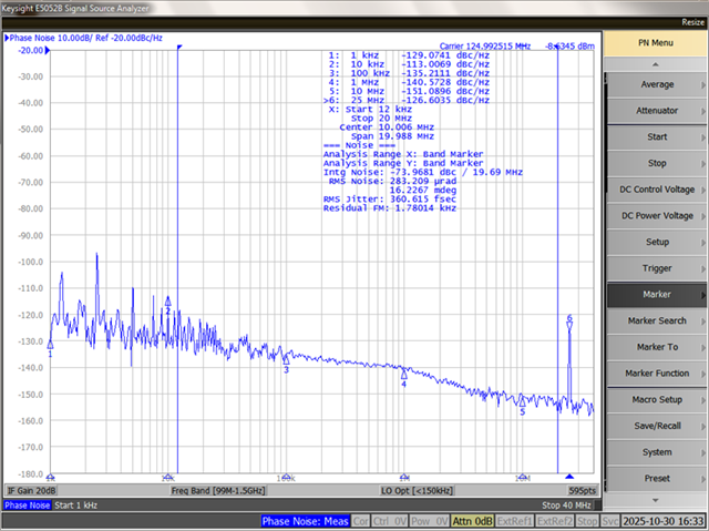
    It depends on the RMS jitter integration range you care about. The input noise primarily affects close-in phase noise while PLL phase noise dominates a lot of the 12kHz to 20MHz integration range. PLL phase noise is correlated to N-divider value, so having a larger input frequency will decrease the PLL phase noise.

    I took some phase noise measurements of Y3 on the bench as an example. 

    Above is the phase noise with the doubler on and N=10. The close-in phase noise has more spurs and there is a large spur at 25MHz, but the 12kHz to 20MHz integration range is only 360fs.

    With the doubler disabled and N=20, the close-in phase noise and 25MHz spur are less, but the integration range is 500fs. 

    So while the doubler does add noise to the input signal, it only affects certain aspects of the output clock performance. 

    Best,

    Cris