This thread has been locked.

If you have a related question, please click the "Ask a related question" button in the top right corner. The newly created question will be automatically linked to this question.

LMK04832: Asking for a review: selected architecture and phase noise

Part Number: LMK04832
Other Parts Discussed in Thread: LMK61E2, ADC3683, CDCLVP111-SP, LMX2615-SP, CDCM7005-SP

Dear All,

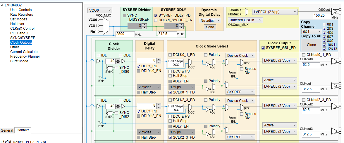
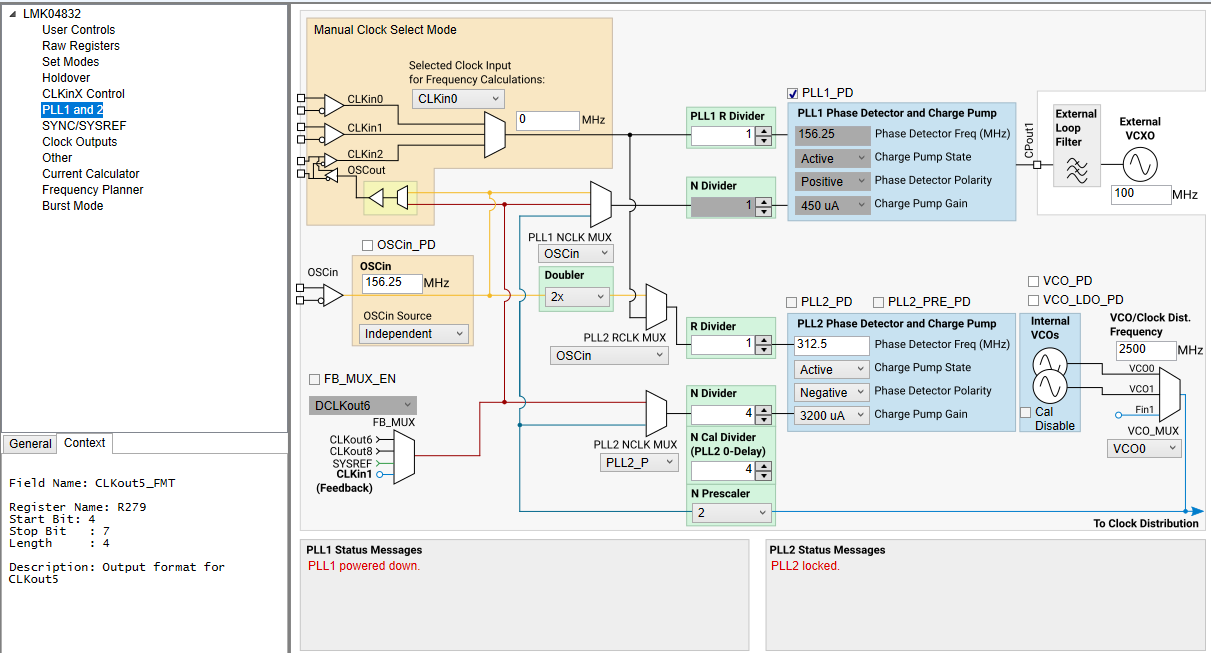
I am using LMK61E2 with LMK04832 to feed seven ADC3683. LMK61E2 is supposed to generate 156.25 MHz for LMK04832, which then generates two clocks, 62.5 MHz and 312.5 MHz, as the sampling frequency (CLK) and digital-interface clock (DCLKIN) for ADC3683s, respectively.

Structure in TICS Pro looks as follows:
obrazek.png

and 

obrazek.png

Modelling in PLLatinumSim looks like this (considering 60 pF internal capacitance on CPout2):

unnamed-1.png

Considered phase noise of LMK61E2 is as follows:

unnamed-1.png

Questions:

.: Do you think that the chosen structure is a reasonable for clock generation for seven ADC3683 chips? Especially might it be acceptable to generate 62.5 MHz on even and 312.5 MHz on odd outputs? Or would you consider it being problematic? I could not find any other configuration how to use single LMK04832 for the purpose of generating these two clocks.

.: As 62.5 MHz and 312.5 MHz does not need to be phase-synchronized for proper operation of ADC3683, do you think it might be wiser, due to possibility of crosstalks on neighbouring clock outputs, to select two separate clock generators ICs? One generating seven outputs with 62.5 MHz clock and the other seven outputs with 312.5 MHz? If this approach would be better, could you please recommend the particular IC which would be also available in space-qualified version?

.: I care about the phase noise characteristics, which I try to minimize. Do you think it might be still possible to squeeze the frequency characteristic in PLLatinumSim a bit below?

Thank you very much for your support!

Regards,

Ondrej


  • Since you have stated you care about the phase noise characteristics, it is worth considering that use of the SYSREF divider and output path will add to your overall noise floor, as it is several dB higher floor than the clock divider and output path. The SYSREF divider noise floor is closer to -157dBc/Hz at 62.5MHz, and is slightly higher at 312.5MHz (not necessarily following the 10dB/decade curve, I think the divider is not the dominant noise contributor on the SYSREF divider path - I don't have exact numbers and it has recently become difficult to quickly check because much of our equipment is moving between sites at the moment). But I think the phase noise numbers PLLatinum Sim would give you for 312.5MHz through the SYSREF divider are quite optimistic compared to real-world measurements. We should add a SYSREF divider floor characterization to our output options to clarify this difference in the software. In any case, it may actually be the correct option to put 312.5MHz on the SYSREF divider, as the SYSREF path penalty may be relatively less for a 312.5MHz output than for a 62.5MHz output.

    It is also worth considering that there will be considerable crosstalk between the two continuous clocks, leading to a 62.5MHz spur on the 312.5MHz clock. Crosstalk spurs may be possible to mitigate or work around in post-processing if you are aware of them ahead of time, but it should be stated that these will be significant crosstalk spurs, likely > -90dBc/Hz; and unless your phase noise analyzer is very good, you'd only notice them on a spectrum analyzer. That said, there are no suitable space-qualified alternatives from TI which would separate the clocks into separate domains and also preserve the desirable phase noise characteristics. The closest alternative (for now) is splitting into two LMK04832s, or an LMK04832 and another buffer device like CDCLVP111-SP - and this will either greatly increase cost or make little difference to the noise performance (CDCLVP111-SP noise floor is probably worse than the LMK04832 SYSREF divider floor). Other clock generators are either poorly-performing relative to LMK04832 (CDCM7005-SP) or are lacking in output count (LMX2615-SP or similar dual-output synthesizer). This might not be helpful right now, but we recognize the specific challenge presented by this kind of problem; keep an eye on our clock buffer portfolio in the future.

    The higher C2 in the loop filter does push down noise in the 10k-20M offsets, but you may have noticed that it increases noise in the 1k-10k offsets. Depending on which offsets are of particular interest to your application, you may consider reducing C2 to lower 1k-10k noise, at the expense of very slight VCO noise increase in 12k-20M band). But otherwise I think you've squeezed about as much out of PLLatinum Sim as it can give you.

  • Dear Derek,

    amazing, thank you very much for the answer and mentioning the slightly higher SYSREF noise floor; I was smelling a possibility of slightly inferior performance here.

    62.5 MHz is used by the ADC for actual sampling, where I care about minimizing the phase noise most. As 312.5 MHz is used by the ADC for digital interfacing, I think that slightly higher phase noise and the spurs from 62.5 MHz might not be hopefully so problematic. So, I will keep configuration as shown in my original post and see how it behaves in practice.

    Again, thank you very much!

    Ondrej