LMX2820: LMX2820RTCT unable to lock

Part Number: LMX2820
Other Parts Discussed in Thread: LMK04832,

Hi, all,

                We have been using LMX2820RTCT for some time in our project.

                Recently we received quite a number of RMA return with failures related to this chip.

                Below is the extracted schematic diagram. All power supplies are 3.3V. Its clock input is 300Mhz from an on board LMK04832NKDR.


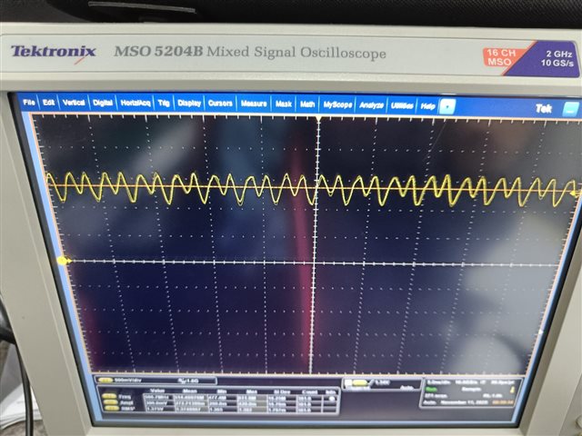
                300Mhz signal seems ok at pin 8.


                The SPI bus is working, able to retrieve the internal temperature register.

                However, the LD pin (pin 38) is toggling from locked to unlocked.


            Replacing the IC does not resolve the issue. 

            Can you please help to advice next steps for troubleshooting the issue? 

  • Hi There,

    Did you check the RF output to confirm it is a real unlock or it is just an issue on the LD pin?

  • Thanks for the reply. RF output is there, but the frequency is a bit off, 2.39995Ghz instead 2.4Ghz as programmed. Is it a concern?

    Recorded the LD pin plot also.

  • Hi HR,

    LMX2820 is locked. If it is unlock, the frequency will be completely wrong. With 300MHz input, 2.4GHz output is an integer channel, output frequency must be exact. The 50kHz difference is likely due to the clock source of LMK04832, if it is not synchronized with the spectrum analyzer. 

    LD is puzzling me, it is a periodic signal, what is the frequency? Are there any control signal having this frequency? Can you measure the Vtune voltage (at the Vtune or CPout pin), is it a static trace or toggling?

  • Hi, Noel,

         Thanks for the follow up.

         I recapture the LD waveform since power on as below,

    The frequency increases from ~100K to about 700K before the waveform becomes flat. 

    The CPOUT (pin 14) is measured as below,

    The frequency also keeps increasing, but never becomes flat.

    VTUNE is measured at around 80mV as shown below,

    The 3.3V supply and SPI signals all look good.

     spi SDI

     SCK

    On the same board, there is another piece of working LMX2820, I measured the CPOUT as below,

  • Hi HR,

    CPout voltage is 1.3V in the working device, this is good, however there are 500mV AC signal as well, I hope this is just a measurement issue.

    on the failure device, CPout voltage is toggling between 0V and 2.4V but Vtune voltage is just 80mV. From the schematic, CPout and Vtune are connected via a 18.2Ω resistor and a 3.3nF shunt capacitor. I expect we should see similar voltage on Vtune pin. Looks to me that there is issue on the loop filter. Please check if you have populated the wrong component values or there is soldering issue.