This thread has been locked.

If you have a related question, please click the "Ask a related question" button in the top right corner. The newly created question will be automatically linked to this question.

TLC555: Unexpected output behavior during power down

Part Number: TLC555
Other Parts Discussed in Thread: TLC3555-Q1, , TLC3555

Hi,

I have issue of unexpected output behavior during power down for TLC555-Q1

The power supply to the TLC555-Q1 turned OFF, causing Vcc to drop.

At approximately 1.6V,OUT malfunctioned, repeatedly cycling between High and Low.

At cursor B position, TRG dropped to low and remained low thereafter.

CH1:Vcc, CH3:OUT

image.png


PS:

I connected a resistor to the VDD capacitor to discharge it, but while the timing changed, the operational state remained unchanged.

The OUT pin will remain high until VDD drops to 1.3V.
If the behavior can be adjusted so that OUT goes low when VDD falls below 1.3V, the system can be made to function properly.
If you have any suggestions, I would appreciate your guidance.


  • Hello TTD,

    As VDD drops, CONT voltage also drops. When CONT voltage is low, THRES pin can override TRIG pin.  Is this a new design? I expect, yes.

    Alternative timer, TLC3555-Q1, should hold output high better. 

  • Hi

    >As VDD drops, CONT voltage also drops. When CONT voltage is low, THRES pin can override TRIG pin.  Is this a new design? I expect, yes.

    Is it correct undestanding below?

    Effects of CONT Voltage Drop During VDD Decline The CONT pin of the TLC555-Q1 determines the reference voltage for the internal comparator (typically 2/3 and 1/3 of VDD). When VDD drops, the CONT voltage also decreases proportionally, causing the threshold to collapse. In this state, the comparison at the THRES pin may override the operation of the TRIG pin, leading to unstable output. This is a design specification: when the new VDD falls below the rated value, the internal circuitry becomes unstable, which is unavoidable.

    >Alternative timer, TLC3555-Q1, should hold output high better. 

     Does the TLC3555-Q1 have a POR feature? If so, does the output remain high even while VDD drops from 5V, and then go low once VDD falls below a certain POR threshold voltage?

    Best Reagrds,

    TTd

  • TTd,

    The trigger internal voltage is 1/3 VDD and trigger comparator goes below TLC555 common mode range (as VDD falls). TLC3555-Q1 trigger VCM range goes below CONT as 0.1V (50mV internally) while VDD > 1.5V

    Does the TLC3555-Q1 have a POR feature?

    This is power down, so under voltage lockout would be issue. I haven't looked a sample data for VDD falling and trigger and threshold asserted. I could try this by the end of the week. UVLO or POR active would likely be output low. 

  • Thank you for your support.

    Thank you for confirming whether the TLC3555-Q1 outputs Low when power is off or if it has a UVLO function.

    Also, just to be sure, is there no other way to avoid this issue with the TLC555-Q1? For example, reset IC hold the reset pin low when power begins to drop(Vdd is still recommended voltages(>2V)), dose output be Low?

    Best Regards,

    ttd

  • TTD

    Ron will need to get back to you Friday.  Sorry for the delay

    Chuck

  • TTD,

    Reset low for output low is the best way to support power down consistency. Add an RL to ground to help.

  • TTD,

    For power down while asserting trigger and threshold while reset is high, TLC3555 sample data suggests no pulling low.

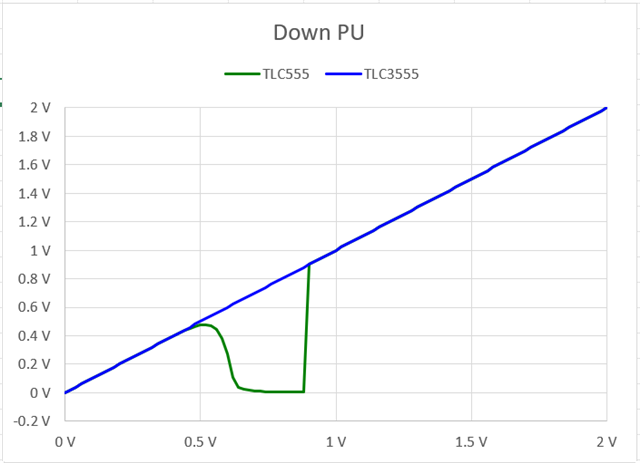
    First chart is VDD power down (moving left on chart) OUT has 100k resistance to 200mV (to see HI-Z output states)

    Second chart is VDD power down while OUT has 100k resistance to VDD (pull up)

    For output high all the way down, a pull up resistor is needed. 

  • Hi,

    Regarding the waveform in the diagram, is the green line the TLC555?

    VDD seems to maintain a high level up to 0.85V.

    The meanings of the X and Y axes are as follows:

    X-axis: Decreasing state of VDD (supply voltage)
    Y-axis: Voltage at the OUT terminal (VOUT)

    Best Regards,

    ttd

  • TTD,

    Regarding the waveform in the diagram, is the green line the TLC555?

    Yes.

    X-axis: Decreasing state of VDD (supply voltage)
    Y-axis: Voltage at the OUT terminal (VOUT)

    Yes.

  • Hi Ron,

    Our actual measurements here show VDD dropping to Low around 1.6V, whereas the your test waveform maintains VDD at High up to 0.85V, resulting in differing outcomes. What factors could be causing this?

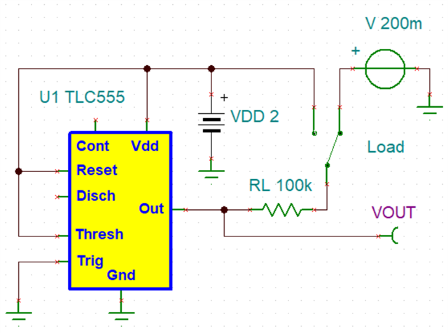
    Could you share your test schematic?

    Best Regards,

    ttd

  • TTD,

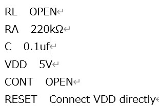
    This was my test circuit. VDD falls slowly, about 1-2 seconds. 

  • Hi Ron,

    Thank you for sharing test cicuit.

    Which test did you evaluate only simulation or IC on board(probe pin) ?

    Best Regards,

    ttd

  • TTD,

    On bench, I would not trust the model for below min VDD operation.

  • Hi Ron,

    Testing with the TLC3555-Q1 appears to have improved the behavior.

    CH1:VDD

    CH3:OUT

    CH4: Pullup voltage

    I forgot to mention this last time, but the OUT pin is pulled up from a separate 5V power supply distinct from VDD.
    The state shown in the waveform above (CH4) is with the OUT pin pulled up.

    With VDD around 1.3V, it enters the OFF state, and since OUT is at the pull-up supply voltage,
    the behavior is as expected.

    Q1
    With the TLC3555, the unstable region of OUT before turning OFF has disappeared.
    Compared to the TLC555, which parameters account for this improvement?

    Q2
    We plan to replace the TLC555 with the TLC3555 without changing the surrounding constants.
    Are there any points to note during this replacement?

    Best Regards,

    ttd

  • TTD,

    For this application I expect no significant change. Below is a comprehensive list of differences. 

    This is a list of things that are different on TLC3555; in the order that better likely has negative ramifications in applications.

    1. Lower propagation delays, make results closer to design simple formulas
    2. Improved ESD performance
    3. Startup circuit added for more reliable start up
    4. Fixed the flaw where THRES can override TRIG, when CONT is less than 2/3 VDD.
    5. Reset pin has internal pull up; allows floating RESET pin.
    6. CONT pin resistive divider changes FET to resistors
    7. Faster rise and fall time

    These are the natural and unexpected side effects of POST-PCN being better

    1. A-stable oscillator will have a higher output frequency
    2. Internal diode on DISCH to VDD prevents having DISCH voltage greater than VDD
    3. Large VDD glitches can upset timing waveform output
    4. Some applications depend on the flawed truth table operation
    5. Reset used with RC networks will ramp differently due to 860k internal pull up
    6. Slightly different CONT pin charge up time with capacitor
    7. More EMI on poorly laid out circuit boards
  • Hi Ron,

    Thank you for the list of differences and the list of points to note.

    Replacing the TLC555 with the TLC3555 eliminated malfunctions during power-off, but now malfunctions occur during power-on.

    CH1(Blue):OUT Voltage

    CH2(Light Blue):TRG Voltage

    Zoom waveform

    After reviewing the situation here, it appears the TRG voltage is involved.
    Originally, the TRG pin was configured with a 47kΩ pull-up resistor from the 5V supply + 1000pF capacitance,
    resulting in a slow rise time for the TRG voltage. Opening this 1000pF capacitor prevented the malfunction.

    ◎Question
    Based on this, I believe the TLC3555 has smaller hysteresis in its TRG threshold,
    and the slow TRG rise time caused multiple trigger detections, leading to this issue.
    Is my understanding correct?

    Best Regards,

    ttd

  • TTD,

    It is same reason as before. 

    As VDD drops, CONT voltage also drops. When CONT voltage is low, THRES pin can override TRIG pin.

    In original TLC555 design, there is a truth table flaw. Ideally TRIG is supposed to override THRES always, but that doesn't happen in some conditions.

    For TLC3555 design, TRIG overrides THRES. So trigger has to be high to prevent starting a timing cycle.  

  • Hi Ron,

    About following REST for TLC3555.

    5. Reset used with RC networks will ramp differently due to 860k internal pull up

    When changing from the TLC555 to the TLC3555, are there any adjustments needed on the board? Please let me know if there are any concerns related to this issue or any other potential issues.

    Best Regards,

    ttd

  • TTD,

    Some applications have an RC network on RESET pin to apply RESET on power up. If a large R value was used then R would be different from R and 860k in parallel.  

    Please let me know if there are any concerns related to this issue or any other potential issues.

    I believe TLC3555 will drop in without any further issues or changes needed.