This thread has been locked.

If you have a related question, please click the "Ask a related question" button in the top right corner. The newly created question will be automatically linked to this question.

LMX2572LP: Modulation sidebands LMX 2572LP

Part Number: LMX2572LP
Other Parts Discussed in Thread: LMX2572

Hello TI Team.

We have developed a VHF and UHF FM transceiver that uses the LMX2572LP for frequency generation. This has worked well, and we have approved the devices with 500 mW transmit power. The operating range of the devices is from 140–175 MHz and 410 MHz to 470 MHz.

Now we had the idea of turning it into a 6-watt device. However, there is a problem with spurious emissions.

We use direct digital FM modulation

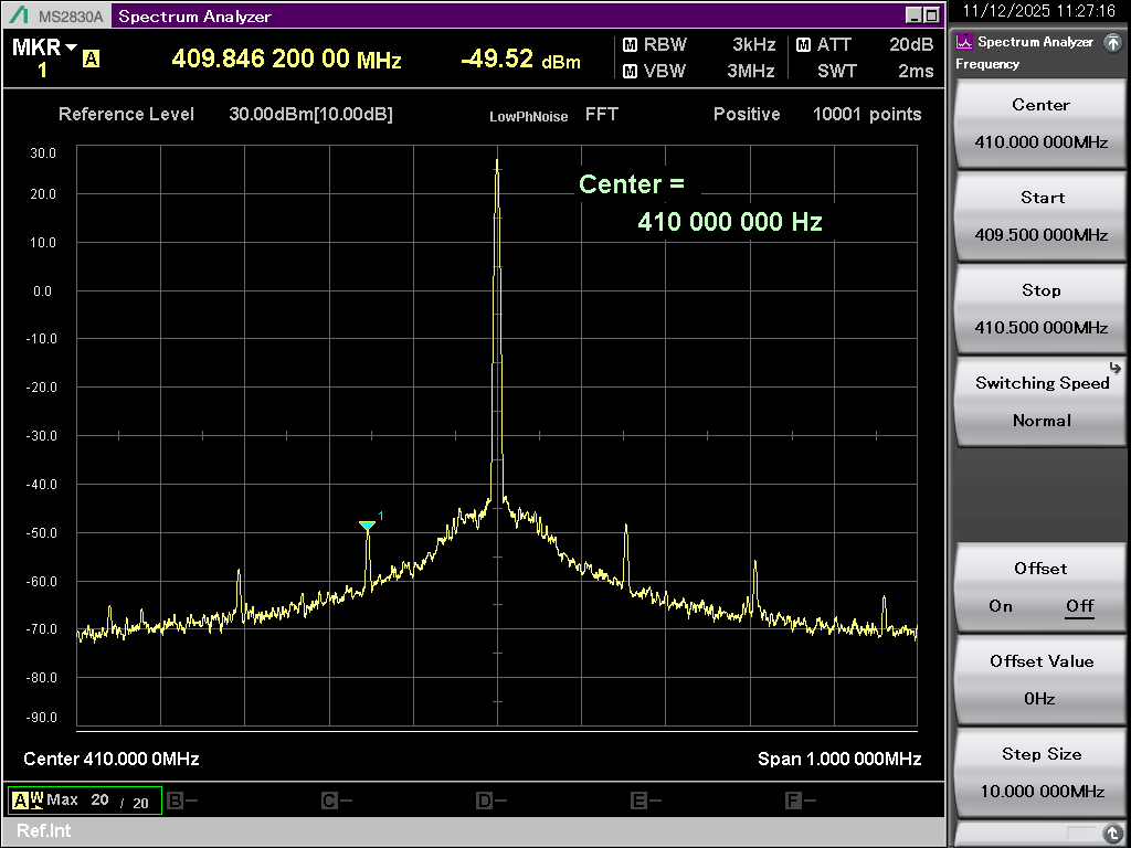
with a sampling rate of 153 kHz. These 153 MHz appear in the spectrum around the carrier.

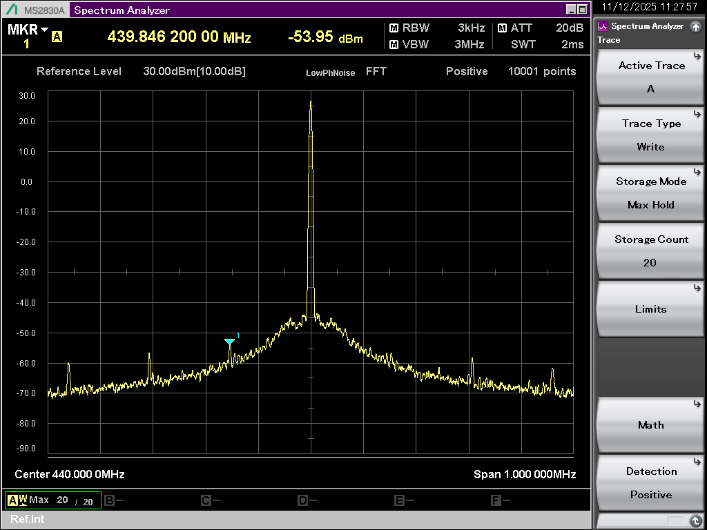
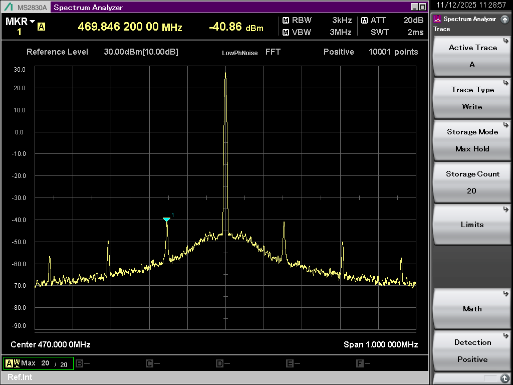
In the VHF range, these spurious emissions are very small and hardly visible, but in the UHF device they are clearly noticeable. In the middle of the band at 400 MHz, they would be within the permissible range, but at the band limits at 440 MHz and 470 MHz, they are too strong for approval because they exceed the required -36 dBm at a transmission power of 6 watts.

We now have the question of why these spurs are so frequency-dependent and what we can do to reduce them. The loop filter is the one from the evaluation board and we are using the lowest charge pump current. With higher charge pump currents, the situation gets worse.

Best regards.

D.W.

410 MHz.bmp440 MHz.bmp470 MHz.bmp

  • The center of the band is, of course, 440 MHz for us, and the band limits are 410 and 470 MHz.

  • Hi Dirk,

    The frequency dependence is due to different VCO is used to generate the frequencies. There are 6 VCO in the chip, you can do a register read back to verify which VCO is being used for the frequency channel you are operating.

    These sideband spurs are difficult to deal with, as far as I know, increasing the sampling frequency helps. In addition, use 1.8V logic to program device also help. Other than these two tricks, I don't have any other good solution to reduce these spurs.

  • Hello Noel.


    Thanks for your reply. We can't increase the sampling rate any further. Maybe we can try the

    1.8V logic. If that doesn't work, we'll have to come up with something else.

    Best regards.

    D.W.

  • Hello.


    We have now determined that the spurious signals are coupled into the LMX 2572LP via the SPI bus.

    The 153 kHz burst from the LMX2572 programming is

    presumably coupled into the VCOs.

    The solution is a new layout for the 6-watt device in which the SPI bus is routed entirely within the inner layers of the circuit board.

    best regards

    D.W.