This thread has been locked.

If you have a related question, please click the "Ask a related question" button in the top right corner. The newly created question will be automatically linked to this question.

LMX2492: LMX2492 ramp issue

Part Number: LMX2492

Hello,

I have been working on creating ramps on a customized board which has an LMX2492 in the design. Initial experiments with Ramps with 5-6 segments have been working. But now we came across a problem.

First, the good case. This has 5 segments, initially starts at a low frequency of 4950 MHz and stays flat, then moves up to the high frequency of 5130 MHz, stays flat for a while and then back down to the start frequency of 4950 MHz. This works fine. The ramp sequence takes exactly 5 msec as desired. The TICSPro Ramp and PLL settings are attached as a screenshot and also the Time vs Frequency plot of the Ramp (please note: the frequency is scaled down by a factor of 208 and centred around 25 MHz). The frequencies and time measurements are perfect as below.


TICSPro-PLL-good-up-down.png

good-up-down.png

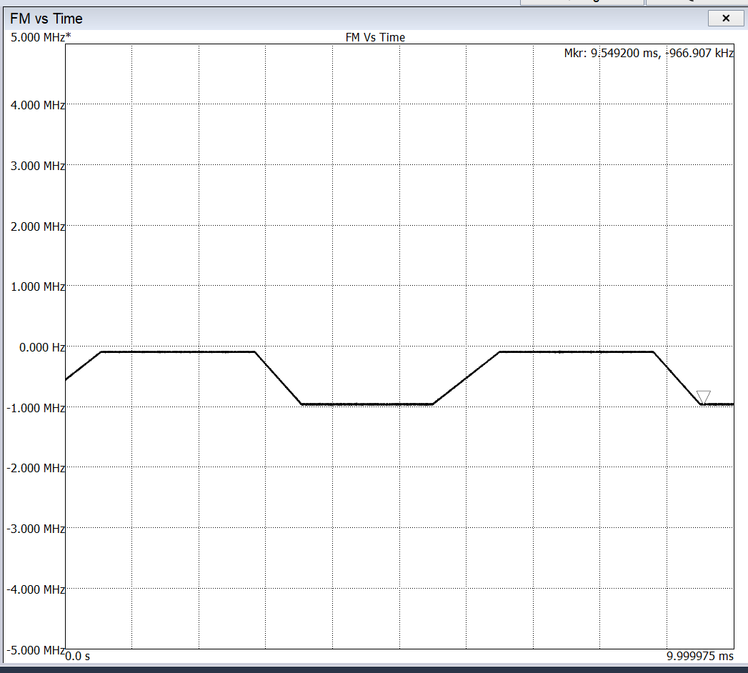
Now, the bad case. This has 6 segments, initially starts at a high frequency of 5130 MHz and stays flat, then moves down to the low frequency of 4950 MHz, stays flat for a while and then back up to the start frequency of 5130 MHz. Note that the frequencies and total time of the intended ramp pattern are same as before but we start from the high frequency this time. This does not work properly. The overall shape is okay but the frequencies achieved in the ramp are not correct and do not match what we intended. Also, the whole sequence is supposed to take 5 msec but here it is taking more like 6 msec. The TICSPro Ramp and PLL settings are attached as a screenshot and also the Time vs Frequency plot of the Ramp, as with the earlier case.
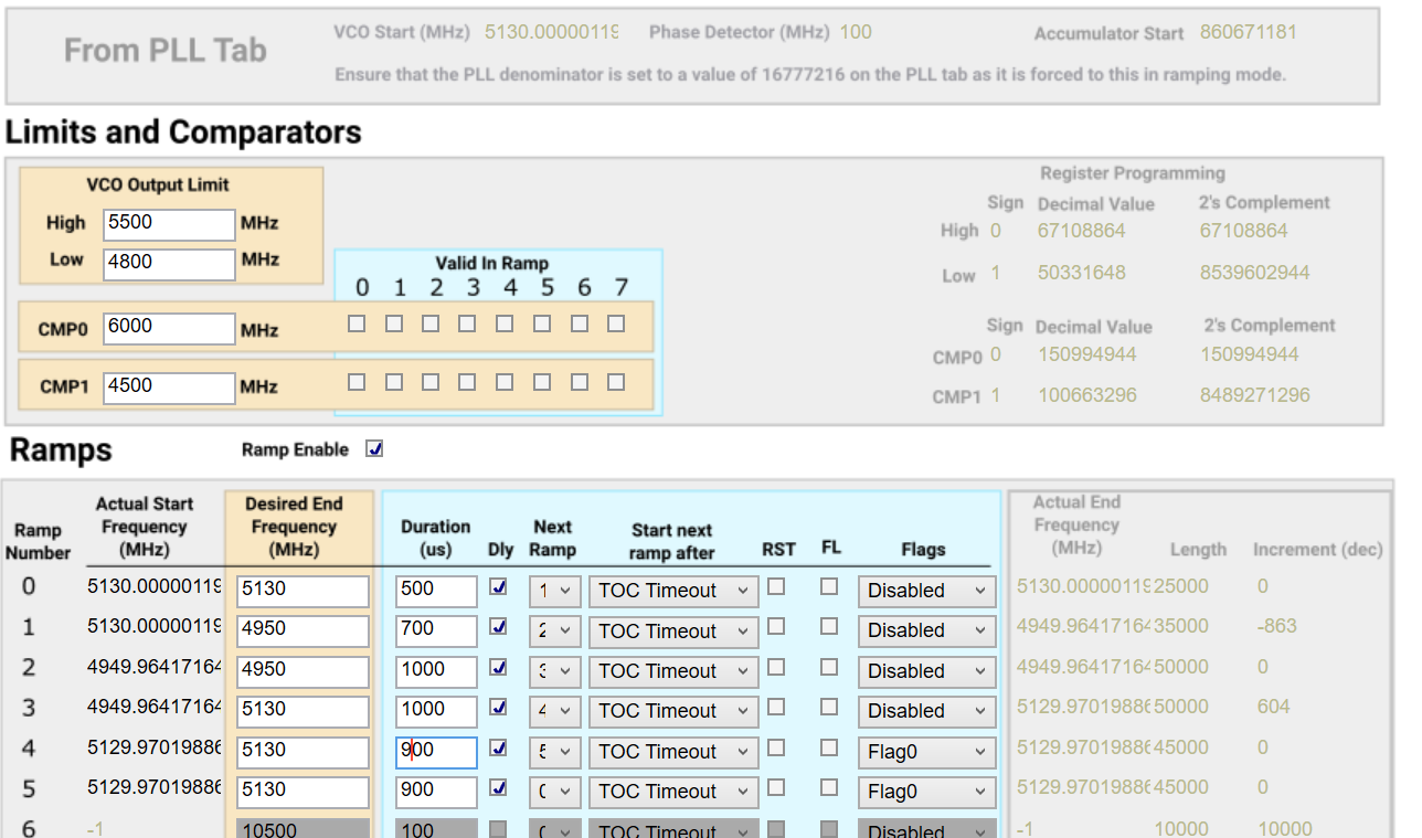
TICSPro-PLL-bad-down-up.png

bad-down-up.png

Sorry for all the details, but this is to illustrate that we have a working ramp but just changing whether we go low -> high -> low versus high -> low -> high is affecting the result: both frequencies and time.


Thanks very much!
Arun


  • Hi Arun,

    I don't see a problem in the configuration. Since your ramp started at 5130MHz, your PLL should lock to this frequency before enabling the ramp. Was your PLL locked to 5130MHz before you kicked start the ramp?

  • Hi Noel,

    Thanks for the quick reply!
    And for confirming the configuration looks okay. That takes a load off my mind.

    Also you hit on what was to be my next question, if configuration is okay then perhaps my procedure is not. I am programming all the registers in decreasing order as mentioned in the datasheet. During this sequence should RAMP_EN be 0 or 1? After the whole sequence is over, which includes everything including the FRAC_NUM and PLL_N settings, I then have two additional steps at the end: RAMP_EN = 1 is programmed and then PLL_N LSB is programmed, I think this follows the datasheet. I have a test triangle ramp pattern and it always works fine so I thought procedure is okay. I have not explicitly checked if PLL is locked before enabling ramping.

    Second question and this popped up just now as a thought since configuration is okay, the RAMP_LIMIT_HIGH/LOW registers remain the same in the configuration, however it seems they are not absolute values and are relative to the starting frequency. I wonder if this is the issue, as down an up ramp to start or doing a down ramp to start, will not affect the config values on TICSPro but I just realised they will affect the actual registers.

    If you confirm the above two questions then I think I'm on my way to solving this.

    Thanks as always for your very prompt responses!

    Best Regards,

    Arun

  • Hi Arun,

    Initialization programming (i.e. after Vcc power up the device), program all the registers in descending order, RAMP_EN = 0. The PLL should be locked to the start frequency of RAMP0 before enabling ramp.

    When the device is locked and ready to ramp, program RAMP_EN = 1. 

    The High and Low limits should be set to beyond the highest and lowest ramp frequencies. You have already set them right.

  • Hi Noel,

    Thanks for the answer. I'm able to get good ramps now. Please see two attached single ramp sequence examples, with different start/end frequencies (5130 MHz in the first case, 5450 MHz in the second case. Plots are centred around 5200 MHz).

    As you can see, I have solved the issue of high to low to high ramp sequences with your help. However, there is one problem still there. After the ramp sequence is over in both cases, after the final ramp segment, the frequency goes to a higher value. In the first case instead of remaining at 5130 MHz it goes up to 5200 MHz and in the second case instead of remaining at 5450 MHz it goes up to 5500 MHz. In both cases, it seems to have gone up to the next highest interger multiple of the OSC frequency of 100 MHz but this could be a coincidence. I'm not able to figure this out. It seems like after exiting ramp mode (because I have set RAMP_COUNT equal to number of segments, and RAMP_AUTO = 1 so that ramping stops at one sequence rather than looping), the LMX2492 is going to some different frequency.

    Please help solve this going to a slightly higher frequency after ramp sequence is over.

    Thanks!

    Best Regards,

    Arun

  • Hi Arun,

    If you are talking about the little glitch, that is due to the loop filter transient response. You can use a smaller time scale to zoom in that glitch.

    The glitch is actually an overshoot, the amplitude of the overshoot depends on the loop bandwidth and phase margin. For example:

  • Hi Noel,

    Sorry, I should have been more clear with my question. Please find attached the annotated image of the ramp sequence, with notes on the desired/programmed (Orange section) and the mystery frequency to which LMX2492 jumps after the ramp is over (Blue section). Since I am getting the perfect Ramp start frequence I presume I have programmed the starting PLL_N, FRAC_NUM etc. correctly. But I don't get why it jumps to some other (higher) frequency after the ramp is done.

    Thanks,

    Arun

  • Hi Noel,

    I worked on this some more and found a temporary solution which was to have the last (flat) segment of the ramp sequence to point back to itself and keep RAMP_AUTO = 0 so that it remains in Ramp mode always, so it never exits, and so it never reaches the Blue section marked above.

    However, as I will be using this IC more in the future, I'd like to understand how to solve my problem. I have one question: how to set FRAC_DEN = 2^24 when RAMP_EN is not enabled? As this is a 24 bit field it runs to (2^24 - 1). Right now I am setting it to 0, does this internally set to 2^24? Essentially I am trying to find what CW frequency it will settle to after exiting Ramp mode and checking registers which affect CW frequency. When exiting Ramp mode, what will FRAC_DEN get set to?

    Thanks,

    Arun

  • Hi Arun,

    I will look into the ramp problem later.

    For the FRAC_DEN configuration, when ramp is not enabled, you can set it to 2^24-1. When ramp is enabled, the chip will automatically use 2^24. 

  • Hi Arun,

    Your plot shown one pulse, I assume you are using an external trigger signal to kick start the ramp.

    The configuration should be something like this:

    Green trace is the trigger signal; pink trace is Vtune voltage.

    RF output will be like this.

  • Hi Noel,

    My apologies for replying so late. I was also thinking that I should set FRAC_DEN to 2^24-1 before enabling ramp. This is probably my problem, as I had left it to whatever I had set for modes without ramping, and then had set the FRAC_NUM to the equivalent of 0.5 as I had to start from 54.5. I assumed that when enabled, FRAC_DEN would be automatically set to 2^24 and as this was not possible to set I'd left it at a value of 1000 which is what I'd used for previous modes.
    However I have not tried with your suggestion value yet as I had found a workaround as mentioned in my previous post (looping last ramp section back to itself) so it never exits ramp mode.

    For now I will mark this as "resolved".

    Thanks,

    Arun

  • Hi Noel,

    I am triggering by writing PLL_N value. I am not using external trigger.

    Thanks,

    Arun