This thread has been locked.

If you have a related question, please click the "Ask a related question" button in the top right corner. The newly created question will be automatically linked to this question.

LMX2572: LMX2572 Ramp issue

Part Number: LMX2572

I have been working on creating ramps on a customized board which has an LMX2572 in the design. Initial experiments with Ramps in sawtooth form.

Trying to ramp in between 2400 to 2500 MHz, the current ramp time i achieved 300 uS. I want to minimize the ramp time to 50 uS or even less... Please suggest the configuration for the LMX registers required.

  • Hi There,

    50µs is not possible. Your ramp range is 100MHz at the output, the VCO ramp range is 200MHz. Linear ramp is not able to support 200MHz frequency change. That means there are several VCO calibrations during the ramp. As a result, 50µs is not possible.

  • Hi Noel, Thanks for the quick response.
    I am working on sawtooth waveform and hence there is no ramp1. Ramp0 is configured with 2400 to 2500MHz, rst is ticked and dly is not ticked and duration is 100 or 50 (though no impact on the waveform timing observed because of duration).

    To achieve best ramp timing, I kept ramp_threshold = 50. I believe this means VCO calibration will take place at every 50 MHz sweep. So, for a ramp of 100 MHz, the VCO will be calibrated only once. Could you please let me know what would be the best possible ramp time achievable with this IC?   

  • Hi There,

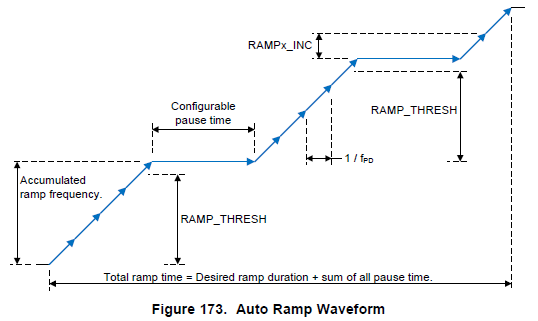
    Please read EVM user's guide (www.ti.com/.../SNAU217) section 3.2.3 for an example, your ramp up waveform will be similar to the example, there are several calibrations during the ramp period.

    Datasheet section 8.1.7.2 has explanation on the timing. 

  • HI Noel, I read the suggested section. The number of frequency spots in the "accumulated ramp frequency" remain unclear. In my case the ramp_threshold is set to 50 MHz, but as number of frequency spots in 50 MHz ramp is not know, I am not able to calculate the time taken!

    Nevertheless, I performed an activity by reducing the desired band from 100MHz to 30 MHz and the observations are as follows:

    The Ramp Time = 5 uSec, for a sweep band of 30 MHz.

    Process to measure the Ramp Time is as follows:

    Spectrum Analyzer span is set to 0 Hz, Frequency set to the band center.
    This give multiple peaks OF band center.

    The delta time between two consecutive peaks is the repetition time of "band center frequency spot".

    This fast waveform is really good.

    Kindly check and confirm the attached image for LMX2572 configurations for this waveform.  

    Configurations are as 

    Fosc = Fpd = 125MHz

    MASH order: 3rd Order

    PFD_DLY_SEL: 3

    Fvco: 4800

    RFoutA: 2400

    Threshold: 50 MHz

    Start Freq: 4880 == 2440 MHz (as CLK_DIV = 2)

    Stop Freq: 4940 == 2470 MHz (as CLK_DIV = 2)

    VCO Calibration time: 0 uS

    RST: ticked

    delay: un-ticked

    nextramp: ramp 0

  • Hi There, waiting for your response.

  • Hi Vanshaj

    Based on your description, here is your configuration.

    The ramp range is 60MHz, so the threshold must be greater than 60MHz.

    The ramp is too fast, we also need to have a wider loop filter bandwidth to support. I used the max. charge pump current setting to widen the loop bandwidth.

    here is the ramp waveform. It is not a sawtooth waveform because the loop response is still not able to follow the ramp rate. 

    if we change the ramp during to 50µs, then we can get the sawtooth waveform.

    Your requirement is difficult to implement with a PLL/VCO. Consider to use a DAC to generate the ramp signal.