This thread has been locked.

If you have a related question, please click the "Ask a related question" button in the top right corner. The newly created question will be automatically linked to this question.

LMK01801: Pin Control Mode connection

Part Number: LMK01801
Other Parts Discussed in Thread: USB2ANY, USB2ANY-UWIRE,

Hi,

In the Pin Control Mode, what is the mechanism of setting for Middle?
Could you something elaborate explanation about it?

According to LMK01801 User’s Guide (SNAU118A – December 2011 – Revised February 2018),
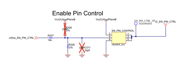
"Headr = Middle" on Table 2 is shown header-pins 3-4 shorted on the schematic.
And it connected to ground via a 27kohm resistor(weak pulldown?).
On the other Hand, "Headr = Low" is header-pins 5-6 shorted to GND directly.
"Headr = High" is header-pins 1-2 shorted to VCC directly.
Are there any voltage-dividing resistors inside the device?

Regards

  • Hi Kamaryu,

    The EN_PIN_CTRL pin is a 3-state logic input.
    It senses the voltage level with comparators to reduce pin count.

    When the EN_PIN_CTRL pin is set high or low (not open) then the output states can be programmed by pins,
    eliminating the need for an external FPGA or CPU.

    The levels are defined as:
    Vih High-Level Input Voltage 2.6 - VCC V
    Vim Mid-Level Input Voltage 1.3 - 1.85 V
    Vil Low-Level Input Voltage 0 - 0.7 V

    When the 3-state input is left floating or the Vim is applied then input current will be zero.
    The 3-state input has divider resistors or two current sources of 100uA.
    This was according the LMK01801 datasheet.

    But now we have the EVM module. It shows us the 27K resistor as (weak) pull-down.
    Without the 27K pull-up it produces just enough current (122uA) to get a logic LOW.
    The USB2ANY interface must have a pull-up resistor to get Vim and configure the LMK in uWire mode.


    Regards,
    Octo

  • Hi Octo,

    I am confusing.
    Is 27kΩ(weak?)pulldown is being applied 3.3V? not (internal) divided voltage 1.65V?

    In the LMK01801 User’s Guide (SNAU118A),
    the sections titled:
     3.1 Quick Start – SPI Mode (TICS Pro) Description
    and
     4.1 Quick Start – Pin Control Mode Description
    mention only the header position, explaining that for the same “Middle” setting, the same schematic/board diagram is used and the same 27kΩ pull-down resistor as is.

    However, necessary to set it “Middle” is not only the header position, but also remove the 27kΩ pull-down resistor or add a 27kΩ pull-up resistor?
    Is it correct?

    Regards,
    Kamaryu

  • Dear Kamaryu,

    The LMK01801 datasheet document shows us the three states for EN_PIN_CTRL: hi, middle, low.
    Designer of the custom board has the choice:
    1. Apply a defined voltage (Vih / Vil) by connecting to VCC or GND.
    2. using resistor to pull-up/pull-down or use two resistors for the middle voltage.

    It is considered a good design practice to avoid floating inputs.
    Furthermore by designing pull-up as well as pull-down resistor on the custom board one can choose the operation mode by altering the populated resistor (even afterwards in the field).

    For the LMK01801 EVM evaluation module the resistor with selector jumper was chosen for fast deployment.
    You are correct regarding the 27KΩ
    resistors in case of stand-alone EVM board (USB2ANY not connected)
    However, the USB2ANY board + USB2ANY-uWire Adapter Board also have a pull-up resistor, and the middle state has been selected for SPI mode.

    Regards,
    Octo

  • Hi Octo,

    So according to the specifications in the LMK01801 datasheet,
    the 27kΩ pull-down resistor on the EVM board(LMK01801BEVAL) is intended to suppress noise, and the input logic state remains at the middle level.
    Even if a maximum current of approximately 61uA(1.65/27k), the potential remains at the middle logic level.
    The High/Low states should be configured to allow a current of 100 μA or more to flow via a VCC/GND connection or through a resistor of 10 kΩ or less.
    Is this correct?

    Regards,
    kamaryu

  • At first glance, yes.
    I only did quick calculations and note that the values ​​in the datasheet electrical characteristics are min/max values.
    Depending on the actual chip the values can vary slightly.
    Normally the controller's lvcmos output port will deliver voltages close to 0.0 or 3.3V and can supply multiple mA so we don't have to calculate.
    I hope your question has been answered.

  • Hi Octo,

    I am very confused again. Sorry for more question.

    I am focusing the followings (on Middle state/voltage level of Pin Control Mode):
      LEuWire/CLKoutDIV_2(pin1), DATAuWire/CLKoutDIV_0(pin47), CLKuWire/CLKoutDIV_1(pin48),
      Test/CLKoutTYPE_0(pin11), SYNC0/CLKoutTYPE_1(pin12), SYNC1/CLKoutTYPE_2(pin40)
    These are I/O=Input , CMOS/3-State.

    7.4 Electrical Characteristics
     DIGITAL INPUTS (CLKuWire, DATAuWire, LEuWire, SYNC0, SYNC1) FOR EN_PIN_CTRL= LOW OR HIGH
      VIH (High-Level Input Voltage) : min 2.6V, max VCC(3.3V)
      VIM (Mid-Level Input Voltage) : min 1.3V, max 1.85V
      VIL (Low-Level Input Voltage) : max 0.7V
      IIH (High-Level Input Current) : max 100uA
      IIM (Mid-Level Input Current) : min -10uA, max 10uA
      IIL (Low-Level Input Current) : min -100uA

    (*Why Test(pin11) pin excluded from this spec? anyway)

    And these pins are internally middle biased.

    My understanding is that IIH/IIM/IIL are the Leak current. (from Gate of CMOS or etc.)But you said,
    “Normally the controller's lvcmos output port will deliver voltages close to 0.0 or 3.3V and can supply multiple mA
    Am I something wrong?

    Regards,
    Kamaryu

  • Hi Kamaryu,

    Right, IIH/IIM/IIL is a form of leakage current to create a defined operating point in this case of 3-level logic input.
    Digital two level inputs often have a internal pull-up or pull-down resistor for stable operation.
    Think of it as a 3-level pull-up/pull-down.
    Indeed middle biased.

    We don't have to worry about the exact voltage level since controlling device or DIP switch deliver voltage close to 0.0V or VCC.

    Regards,
    Octo

  • Hi Octo,

    Yes that makes sense.
    I am not warry about Hi/Lo level.

    Thus my final question, @Pin Control Mode,
    I think, so there are internal bias(pullup/down) for middle level, these pin(ex. CLKuWire) can be left floating same as EN_PIN_CTRL pin.(That’s not unstable)
    Or, it is form of 3state but not same exactly, and these pin can’t be left floating for some reason?

    Sincerely,
    Kamaryu

  • Dear Kamaryu,

    Yes, the inputs can be left floating, LMK01801 has internal pull-up/down provided.
    The datasheet SNAS573D provides the accurate information in the chapter "12.1.1 Pin Connection Recommendations"

    12.1.1.4 Unused GPIO (CLKoutTYPE_X)
    Unused GPIO pins can be left floating. Alternatively, unused GPIO pins can individually be pulled to GND.


    Regards,
    Octo

  • Thank you very much for patiently answering my repetitive questions.