


Part Number: LMX2594
Question:
Could you please advise on the necessary settings and design considerations to achieve this design goal?
Our design goal:
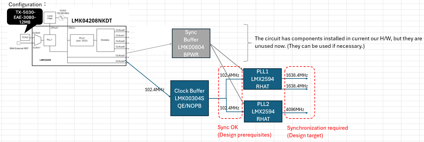
In the following hardware configuration, we would like to achieve phase synchronization by setting the final stage to 1638.4MHz and 4096M.
(Phase synchronization definition: Synchronization of 5 periods of 1638.4MHz and 2 periods of 4096M as below figure)

We have confirmed via oscilloscope observation that the 102.4MHz input to PLL1/PLL2 is synchronized in current H/W.
Could you please advise on the necessary settings of LMX2594 and design considerations to achieve this design goal?
We have also attached our proposed settings in a below table, so we would appreciate it if you could check for any problems with these settings.
In particular, we would appreciate answers to the following:
1. Is it necessary to make the lengths from LMK00304S to PLL1/PLL2 equal?
2. Is synchronization possible even without using the Sync Buffer?
Setting Table
| Register / Parameter | PLL1 config | PLL2 config | Remarks / Common Conditions |
| OSC_2X | 0 | 0 | Doubler disabled |
| MULT | 1 | 1 | Multiplier bypassed |
| PLL_R_PRE | 1 | 1 | R pre-divider |
| PLL_R | 1 | 1 | R divider (fPD = 102.4 MHz) |
| PLL_N (R36) | 96 | 80 | N divider (Integer-N mode) |
| MASH_ORDER | 0 | 0 | Fractional disabled (Integer mode) |
| CHDIV (R75) | code 2 (/6) | code 0 (/2) | Channel divider |
| SEG1_EN | 1 | 1 | Segment 1 enabled (*Verify for Config 2) |
| OUTA_MUX / OUTB_MUX | 0 | 0 | Channel divider output |
| OUTA_PWR | 19 | 19 | Output power setting |
| OUTB_PWR | 29 | 29 | Output power setting |
| OUT_ISET | 0 | 0 | Max output current setting |
| OUTA_PD / OUTB_PD | 0 | 0 | RFoutA / RFoutB output enabled |
| MASH_RESET_N | 1 | 1 | MASH reset released |
| POWERDOWN | 0 | 0 | Normal operation |
| RESET | 0 | 0 | Reset released |
| FCAL_EN | 1 | 1 | VCO calibration enabled |
| VCO_PHASE_SYNC | 0 | 0 | Phase sync disabled |
| RAMP_EN | 0 | 0 | Ramp (frequency sweep) disabled |
| MUXOUT_LD_SEL | 1 | 1 | MUXout pin: Lock Detect output |
| CPG | 7 | 7 | Charge pump current: 15 mA |
| SYSREF | Disabled | Disabled | SYSREF output unused |
| INPIN_IGNORE | 1 | 1 | External input pin settings ignored |
| VCO Frequency | 9.8304 GHz | 8.1920 GHz | Calculated value (Within 7.5 to 15 GHz range) |
| RFoutA / B Frequency | 1.6384 GHz | 4.0960 GHz | Final output frequency |


