LMK04828: Maximum OSCin frequency

Part Number: LMK04828

I would like to know if it is possible to drive the LMK04828 'OSCin' and 'OSCin*' inputs at frequencies between 500 MHz - 600 MHz.

It is understood that the LMK04828 datasheet specifies a maximum frequency of 500 MHz, but I am wondering if under any specific circumstances this input can support higher frequencies?

Note we are currently using differential, AC coupled, LVDS input clock.

Any information is much appreciated!

Thanks

  • While you're welcome to try it and see if it works, we can't make any guarantees that the device will meet the specs in the electrical characteristics.

    The OSCin input stage is largely a copy of the CLKin input stages at the design level, which are suitable up to 750MHz. The PLL2 R-divider is also unlikely to be a problem, and the PLL1 N-divider is definitely not a problem. The OSC_2X multiplier will not work reliably at these frequencies and should not be used.

    I'm not sure OSCout can support >500MHz, I've never tried. The FB_MUX can drive OSCout, and those clocks can be >500MHz, so I think it should work.

    There is a state machine clock divider tapped from the OSCIN port, which divides the clock input by 1, 2, 4, or 8. This state machine clock is supposed to stay below 65MHz to reliably calibrate the VCO when writing the LSBs of the PLL2_N field. At 600MHz, the state machine clock at maximum division is 75MHz, which may cause the calibration to fail or become stuck, which may leave the PLL in an unknown state until reset/power cycle. In principle, it is possible to calibrate the VCO at a lower OSCIN frequency that results in the same VCO frequency, read back the calibration results, and subsequently configure the device to skip calibration while manually entering VCO calibration coefficients. These coefficients should not change over the lifetime of the device, and depend heavily on the temperature at which the calibration is performed; if a fixed set of calibration coefficients is to be used, they should be derived at around the midpoint of the operating temperature range expected in the application. Of course, the calibration coefficients are derived for a specific VCO frequency - if a large range of potential VCO frequencies is needed, it may be feasible to generate a per-device lookup table for each required value. I don't know if we have ever documented the process of overriding calibration coefficients for LMK04828, but if this is of interest I can put something together for you.

  • Hi Derek,

    Thank you for the very informative and rapid response.

    I will try 600 MHz and see how it goes! As for the state machine max clock rate, if it is an issue that could be present over PVT, your proposed workaround of performing a one-off calibration at lower OSCin, storing in NV, and setting this manually going forward, sounds like something we would be keen to explore.  We currently follow a similar scheme for other synths/PLLs within our system but have never done this for an LMK0482x.

    If it is possible to provide brief documentation on the expected process that would be very useful!

    Thank you for any information you can provide.

    Kevin

  • Okay, I've pulled together a basic procedure:

    1. Write all registers normally, with a configuration that uses OSCin at a frequency within specifications
    2. Write LSBs of PLL2_N (R360, 0x168) to trigger a calibration. The PLL should lock after calibration (it may start locked or unlocked, not an issue)
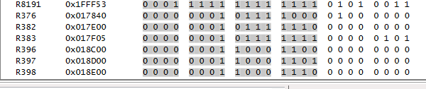
    3. Read back the following registers after successful calibration and capture the values, the temperature, and the nominal VCO frequency:
      1. R396, 0x18C[6:0]
      2. R397, 0x18D[5:0]
      3. R398, 0x18E[2:0]
    4. If building a larger lookup table, repeat steps 1-3 across temperature/frequency as needed
    5. For all subsequent programming cycles where OSCin exceeds frequency specifications (or in general, to use the calibration coefficients without triggering a calibration routine), set PLL2_FCAL_DIS = 1 (R358, 0x166[2])
    6. To manually program the calibration coefficients for a particular VCO frequency and temperature:
      1. R376, 0x178[7:0] = 0x80 | (data from 0x18C[6:0])
      2. R382, 0x17E[7:0] = 0x08 | (data from 0x18E[2:0])
      3. R383, 0x17F[7:0] = 0x40 | (data from 0x18D[5:0])

    The portion of each register write in step 6 that comes before the bitwise OR enables the manual override for the corresponding field that controls some aspect of VCO calibration. I haven't tested this procedure in full, but a subset of it with R396 and R376 had the expected effect of changing the VCO frequency centering (observed by measuring the CPout2 voltage while stepping R376 up and down by several codes), and the design-documented names for the other fields correspond to expectations of settings that are relevant to calibration.

    The LMK04828 calibration coefficients should remain valid for ±125°C from the calibration temperature, so full coverage of the operating temperature range could theoretically be captured anywhere in the recommended ambient temperature range. Calibrating near the midpoint of the expected operating temperature range achieves the best single-point results. Multiple calibration coefficients can be captured in a lookup table, and the calibration coefficients can be updated in real-time as system temperature changes, which could yield very slightly better VCO noise performance (±1dB). Note that updating R376 changes the tuning voltage required for the nominal VCO frequency, which can change charge pump pulse timings slightly and result in a step change in input-to-output phase offset; this has implications for multi-device synchronization and zero-delay mode use cases.

    Of course, TICS Pro does not make it easy to test this procedure, as the relevant registers are undisclosed and not included in the device profile. If you are performing SPI reads and writes through your own programming stack, this isn't an issue. For evaluation with TICS Pro, the device profile must be modified:

    1. Open the file C:\ProgramData\Texas Instruments\Tics Pro\Configurations\Devices\Clock Generator-Jitter Cleaner (Dual Loop)\LMK0482x\LMK04828B\LMK04828B.ini
    2. In the [REGISTERS] section:
      1. Add six to the value of the COUNT key. e.g. COUNT=136 should be updated to COUNT=142.
      2. Anywhere in the section, add the following data (substituting the range 136:141 in keys for the values <COUNT-6>:<COUNT-1> as appropriate):

        NAME136=R376
        MASK136=0
        VALUE136=96320
        NAME137=R382
        MASK137=0
        VALUE137=97792
        NAME138=R383
        MASK138=0
        VALUE138=98053
        NAME139=R396
        MASK139=0
        VALUE139=101376
        NAME140=R397
        MASK140=0
        VALUE140=101632
        NAME141=R398
        MASK141=0
        VALUE141=101888

      3. If TICS Pro is open, close TICS Pro or switch to a profile other than LMK04828B.
      4. If there is a file C:\ProgramData\Texas Instruments\Tics Pro\Configurations\Devices\Clock Generator-Jitter Cleaner (Dual Loop)\LMK0482x\LMK04828B\LMK04828B.tcb, delete it or remove it from the directory.
    3. On subsequent access to the LMK04828B device profile, TICS Pro's raw registers should now expose the relevant registers at the bottom of the page.
  • Hi Derek,

    Again, thank you for the fast and detailed response - we will investigate and implement the procedure ASAP if required.

    Kevin