


Part Number: TMS570LC4357-SEP
Other Parts Discussed in Thread: TMS570LC4357
Hi,
I’m looking for technical guidance regarding the grounding of a 4‑pin crystal connected to the TMS570LC4357. The TMS570LC4357 provides a dedicated Kelvin GND reference for the oscillator.
But our crystal has two GND pins (pin 2&4) : 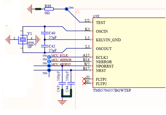
My understanding is that the ground pin of the crystal should be connected to the MCU’s Kelvin GND, just like the load capacitors C40 and C42. In this configuration, the ground guard ring around the crystal would also be tied to Kelvin GND. If yes I should to update my schematic as following :
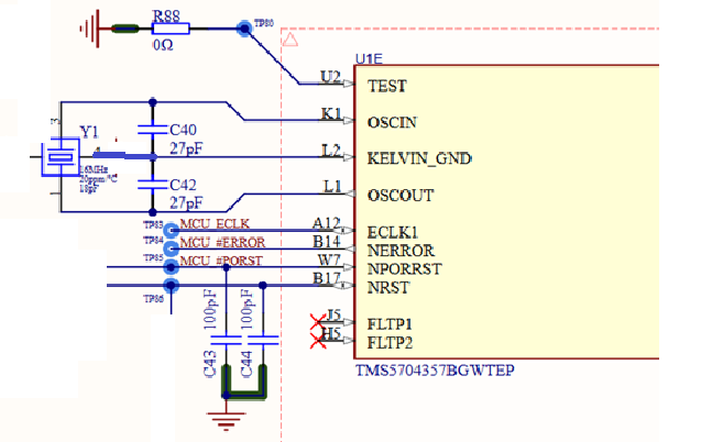
OR Should the crystal’s two GND pins instead be connected to the main PCB GND  , with the guard ring referenced to the board ground rather than Kelvin GND?
Thanks in advance for your support.
Jerome.
