This thread has been locked.

If you have a related question, please click the "Ask a related question" button in the top right corner. The newly created question will be automatically linked to this question.

cdce62002 at 1GHz

Other Parts Discussed in Thread: CDCE62002

We have a cdce65005 providing a relatively low jitter 1GHz output from a 25MHz input.

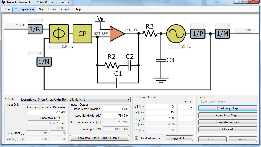
However for a new PCB where space was more of an issue we selected the cdce62002. Having bought the EVM board we cannot get lock with a 25MHz input & VCO = 2000MHz.

Table 3 in datasheet SCAS882D states this is possible. Can it be done on the eval board? Preferably with the internal compensation values?

Thanks j

  • Hi Jules,

    There should generally be no problem to do this. Please make sure of the following:

    1. If you use the primary input, be sure to configure the input buffer properly (e.g. enable or diable input buffer termination, select the right input signaling level, and AC or DC termination). The EVM is AC coupled, so you want to select AC termination.)

    2. If you plan using the secondary input, be sure the XTAL is installed properly.

    3. Click on SmartMux and be sure to select the right input.

    4. What happens if you click on /PD or on the PLL RESET button? this should generate a device calibration. Is the calibration word higher than 1 but lower than 63? If so, the device calibrated properly. If not,  your signal source was not received properly.

    5. Be sure to configure input divider and all feedback divider to run the PDF frequency at 25MHz. Also, make sure to set the internal loop filter with C1=1.5pF, R2=2.7k, C2=473pF, R3=5k, C3=2.5pF, the ICP=500μA. This loop filter should work, though what I don't like is that gamma is only 0.052. This seems low, but I can't find any internal loop filter with a higher gamma.

    6. The safest loop filter would be an external loop filter:

    C1: 3nF

    R2: 154

    C2=100nF

    ICP=3.75mA, R3=5k, C3=38pF


    7. If at this point you still have issues, see what happens if you use a 100MHz reference and adjust the feedback + prescaler division by 4x (to run fPFD=100MHz). Is it working now?


    Best regards, Falk Alicke

  • Hi Fritz,


    Thanks for the prompt and comprehensive reply.

    It seems our problem was that we were not writing values to the EEPROM and so calibration was being done against the wrong values. After doing that it is basically working.

    Some questions on details from your post (your numbers):

    5. Neither the datasheet or the GUI offer the ICP value you suggest. But then DS and the GUI don't match each other.
    a) You suggest ICP =500uA, this is not shown on the GUI (v1.1.8) it lists 200, 300, 400 & 600uA.
    b) The datasheet Table 18, lists ICP options 150,250, 400 & 1500uA.
    According to the datasheet, R2=2k7 is available with ICP 150 or 200uA. To clarify could you specify LFRCSEL[3:0] value?

    6. External Loop
    a) Noted. For external loop components LFRCSEL[3:0] = 0xF.
    b) You seem to have a loop filter tool specific to the cdce62002 . I only found a general on v 1.01 See picture. Can we access the cdce62002 version?

    Thanks again jules