This thread has been locked.

If you have a related question, please click the "Ask a related question" button in the top right corner. The newly created question will be automatically linked to this question.

HCSL to CDCLVP1208

Other Parts Discussed in Thread: CDCLVP1208

Hi

I am using the CDCLVP1208 to distribute a 100MHz differential clock.

The input to the CDCLVP1208 is an HCSL output from a clock generator on the same board.  They are physically very close, 1-2 in.

How should I terminate this HCSL to CDCLVP1208?

AC or DC is acceptable.

All the parts are running at 3.3V.

I have researched this and am still unsure of what the correct termination is.

One source of my confusion is that the CDCLVP1208 has LVPECL/LVDS inputs.

Thanks


  • Lance,

    Fortunately, this can be done passively. However, since HCSL is typically ground referenced, and LVDS is not, you will need to incorporate AC termination so as to set your seperate DC Bias or "Common Mode Voltage" on both sides.

    HCSL is current driven, typically being terminated over 50 Ohms. Start with a 50 Ohm termination resistor to ground for both the +/- outputs on the HCSL side. Follow this with your transmission line and finally your AC coupling capacitor (100nF should work).

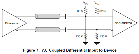
    After the coupling capacitor, you will need to set a DC bias, provide impedance matching to reduce signal reflections and "ringing" which become sources of noise, and make sure the new LVDS signal has the proper high and low levels. HCSL typically has a 0mV to 700mV swing about 350mV. LVDS usually has a 350mV swing about 0.9V. Therefore in most applications, you would need to attenuate the signal on the receiver side.

    However, since the CDCLVP1208 has the ability to accept higher swings on the input due to the Universal Inputs, you can ignore the attenuation and just provide a proper Common Mode and Impedance match. Figure 7 in the datasheet will meet the requirements on the receiver side for LVDS:

    Remember, however, to terminate the HCSL transmitter output with the 50 Ohm resistors to GND before the transmission line. I hope this helps. Please let me know if you have any more questions. Thanks!

    Regards,

    Brandon Vonk