This thread has been locked.

If you have a related question, please click the "Ask a related question" button in the top right corner. The newly created question will be automatically linked to this question.

Glitch-less or Hitless switching problem of cdce62005

Other Parts Discussed in Thread: CDCE62005

Hi:

   I'm using cdce62005 with spartan6 FPGA, cdce62005 works as a jitter cleaner for the gtp 125MHz reference clock, it works fine. I can get a stable recovered clock from the gtp. Now I want to switch the clock source of the cdce62005 from a local 125MHz clock to the recovered 125MHz clock, after switching for some micro seconds, cdce62005 loses lock. The only clock source for me is sec_ref, so I implement a internal mux  to do the switch job. 

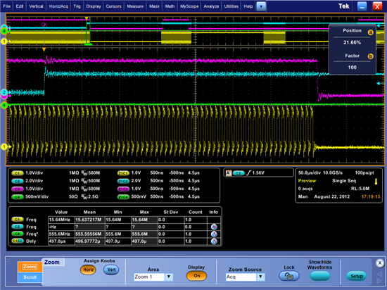
   The clock switch happened at the rising edge of the blue channel, the red channel represents the cdce62005 lock signal, the yellow one is the aux_out which is 1/8 of  the reference clock(sec_ref)   .From the waveform I didn't see any obvious change before and after the clock switching, I can't understand why cdce62005 can't lock at the new clock.

   At my last design I used a si5368 as a jitter cleaner and there is a  Hitless switching function which makes the switch quite easy, is there any similar function in cdce62005 ?

  My register setting is as below: reg8 is actually reg6 , I use it to initial a calibration.

#define reg0 0xe9040300
#define reg1 0x68040321
#define reg2 0xe9040302
#define reg3 0xe9040203
#define reg4 0x68040334
#define reg5 0x500c0eb5
#define reg6 0xb05e0366
#define reg7 0xbd887447
#define reg8 0x945e0366

   Thank you very much in advance for your kindly help.

  • Hello Yifan,

    first of all, why don't you use the internal "smart mux" functionality to switch between both clocks? You could save the external mux.

    If the Yellow signal represents the AUX signal which shows 1/8 of the reference clock, then it is clear that the CDCE62005 looses lock. It seems like your recovered clock disappears which causes the PLL unlock. As i can see from the not zoomed part of the scope plot the device recovers lock after the reference signal is valid again.

    Could you please verify if the recovered clock is stable?

    If you would connect the local 125MHz clock to SEC_REF and the recovered 125MHz clock to PRI_REF you could avoid the problem by using the internal smart mux which switches automatically if one source fails. Register settings for this solution:

    reg0 0xe9040320

    reg5 0x500c0ef5

    The Smart Mux function is described at page 42 in the CDCE62005 datasheet.

    Best regards,

    Julian

  • Dear Julian:

              Thank you very much for your reply.

              First: because we are lack of pins on the spartan 6 FPGA, so I just use the sec reference and the aux_in.

              Second: The recovered clock highly relies on the data link, and the data link highly relies on the output of cdce62005, the system initially work with a local clock , and the recovered clock is stable, after switching to the recovered clock, before the cdce62005 lock to the recovered clock, the data link is not stable because of the unstable cdce62005 output , thus the recovered clock is not stable, it's a loop.

             Since I don't have pri connection, I managed to implement a auto switch from aux_in to sec. The aux_in is 31.25MHz and the sec input is 125MHz , the reference divider is 4, so that the reset of the setting is the same for both aux_in and sec. Aux_in is always valid, sec input firstly connects to 0 and then connects to recovered clock after getting a stable data link, result is still the same, cdce62005 lose lock result in an unstable data link.

             Could you please tell me how can I use the holdover mode, maybe it can help.

    #define reg0 0xe9040300
    #define reg1 0x68040321
    #define reg2 0xe9040332
    #define reg3 0xe9040103
    #define reg4 0x68040334
    #define reg5 0x50000ff5
    #define reg6 0xb05e0366
    #define reg7 0xbd90b8b7
    #define reg8 0xb45e0366