This thread has been locked.

If you have a related question, please click the "Ask a related question" button in the top right corner. The newly created question will be automatically linked to this question.

LMK01000 terminations.

Other Parts Discussed in Thread: LMK01000, LMK02000, LMK01801, LMK00304

Hello,

I am currently working on a design that contains two LMK01000s and I would appreciate some assistance with properly terminating my signals.  The datasheet only specifies that CLKin signals are AC coupled but I don't see any data about impedance.  The CLKout discussion (Section 3.4) is apparently a paste from another data sheet that refers to the OSCin pins on the LMK01000.  I get a little nervous when the specifed pin doesn't exist on the part being discussed. The only LMK specific examples are in section 3.5 about sine wave inputs.

I have two specific cases to implement.
First case has an LMK01000 LVPECL output from the first LMK01000 driving a CLKin for the second LMK01000.  I have the emittier resistors at the driving pins but what termination should I implement on the LMK01000 input for LVPECL?
Second case has a 1:1 BALUN driving the other CLKin for the 2nd LMK01000.  What termination should I have on the LMK01000 input for the 50ohm signal? On which side of the blocking caps?

I also have one last question about the LMK01000 Eval Board.  Both CLKin pairs show non-populated caps to ground on the negative input inside the blocking caps.  Are they a necessary precaution?

Thanks,

  • Harold Dean said:
    The datasheet only specifies that CLKin signals are AC coupled but I don't see any data about impedance.

    I will check into this and update you.

    Harold Dean said:
    The CLKout discussion (Section 3.4) is apparently a paste from another data sheet that refers to the OSCin pins on the LMK01000.


    Yes.  Earlier in the datasheet at the pin descriptions a comment is made about the pin compatible nature of the LMK010x0 with the LMK02000 and LMK030xx families.  This is were the copy-paste comes from.  I think you're right it would be more clear in the latter part of the datasheet if we used the actual pin names for this specific device vs. the pin compatible names of the other devices.


    Harold Dean said:
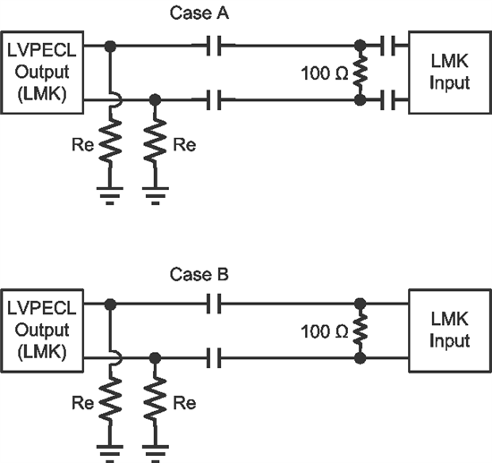
    First case has an LMK01000 LVPECL output from the first LMK01000 driving a CLKin for the second LMK01000.  I have the emittier resistors at the driving pins but what termination should I implement on the LMK01000 input for LVPECL?

    If you are using AC coupled LVPECL, case A is the traditional approach.  You could save 2 capacitors by using case B.  Provided that LMK input is protected from external DC bias.


    Note  - Emitter resistors can be greater than 120 ohms to reduce Icc draw.  I often find 240 ohm resistors to be a good value to minimize Icc draw and with good output amplitude.


    Harold Dean said:
    Second case has a 1:1 BALUN driving the other CLKin for the 2nd LMK01000.  What termination should I have on theLMK01000 input for the 50ohm signal? On which side of the blocking caps?

    What frequency and amplitude is the single ended 50 ohm signal?  What is the reason you are using the balun vs single ended into the LMK01000 directly?  Is this a sine wave/what's the slew rate otherwise?  I might recommend a pad on the input to balun.


    Harold Dean said:
    I also have one last question about the LMK01000 Eval Board.  Both CLKin pairs show non-populated caps to ground on the negative input inside the blocking caps.  Are they a necessary precaution?


    The cap to ground footprints are to allow for allowing single ended input using either CLKin inverting or non-inverting pin.  AC couple signal into one pin.  AC ground the other.  As shown in section 3.5.

    73,

    Timothy

  • Hi Timothy,

    Thanks for the prompt reply and the assistance.

    To follow up on the BALUN.  The clock source is a user supplied input clock.  The input will be a sine wave and the frequency will usually be above 1GHz.  I can specify the required amplitude range.  I am currently planning to use a TC1-1-13MA+ BALUN like TI's ADC-WB-BB BALUN board.  The BALUN board shows the BALUN output AC coupled into 100 ohms to create a 100 ohm impedance.  Since I don't know the LMK input structure I'm not sure what I need to do for the cleanest input match to the LMK.

    One additional LMK01000 question has come to mind.  The LMK01000 is rated up to 1.6GHz.  Is there anything currently that is pin compatible that is rated up to 1.8GHz? 

    Thanks again.

    Harold

    .

  • Harold Dean said:
    To follow up on the BALUN.  The clock source is a user supplied input clock.  The input will be a sine wave and the frequency will usually be above 1GHz.  I can specify the required amplitude range.  I am currently planning to use a TC1-1-13MA+ BALUN like TI's ADC-WB-BB BALUN board.  The BALUN board shows the BALUN output AC coupled into 100 ohms to create a 100 ohm impedance.  Since I don't know the LMK input structure I'm not sure what I need to do for the cleanest input match to the LMK.

    At these high frequencies, use of a balun isn't strictly necessary.  As can be seen from figure 13, at the high slew rates of 1 GHz, performance is very good.  Unless you have other reasons for use of balun, I'd say a 1 GHz sinewave can be input single endedly very well.  I'd use a pi pad for input termination.

    Harold Dean said:
    One additional LMK01000 question has come to mind.  The LMK01000 is rated up to 1.6GHz.  Is there anything currently that is pin compatible that is rated up to 1.8GHz? 

    There is not.  Keep in mind LMK01000 divider is limited div-by-2 above 1.3 GHz.  We have the LMK0030x which is distribution only which can go higher in frequency - if you don't need dividers, this can provide best noise performance since it is simple fan-out.  Also the LMK01801 which can go higher in frequency.  But the most distribution/divide/high frequency flexibility would come from using an LMK0480x device in distribution mode.  Keep in mind LMK0480x even has digital delay.  (LMK01801 has digital delay on one pair of outputs).

      - Are you using the divide or delay features of the LMK01000?

    73,

    Timothy

  • Hi Timothy,

    Thanks for the info. 

    I'm not using the delay or divider features.  I switched over to the LMK00304.  In addition to the performance the smaller package is a bonus.  Since it's an LMK part I assume the termination on the inputs is the same as you recommended before.

    Thanks

    Harold

  • Regarding the input termination for LMK00304, Case B from Timothy's earlier post will work fine.

    Regards,
    Alan