Other Parts Discussed in Thread: CDCM6208V1, CDCM6208
Hi,
I have received a development board with CDCM6208V1 clock generator and am currently experiencing problems if you guys could help?
I am operating the device in pin mode with the following specifications:
|
SI_MODE |
10 |
|
Pin[4:0] |
0x1B |
|
fin (PRI_REF) (TYPE) |
n/a |
|
fin (SEC_REF) (TYPE) |
25MHz (Crystal) |
|
f(PFD) |
25MHz |
|
f(VCO) |
2500Hz |
|
fout(Y0) (TYPE) |
100MHz (PECL) |
|
fout(Y1) (TYPE) |
100MHz (PECL) |
|
fout(Y2) (TYPE) |
250MHz (PECL) |
|
fout(Y3) (TYPE) |
250MHz (PECL) |
|
fout(Y4) (TYPE) |
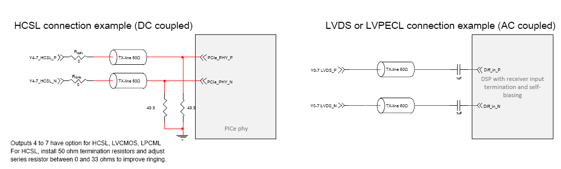
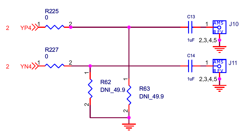
100MHz (HCSL) |
|
fout(Y5) (TYPE) |
100MHz (HCSL) |
|
fout(Y6) (TYPE) |
125MHz (HCSL) |
|
fout(Y7) (TYPE) |
66.67MHz (HCSL) |
I am not seeing any clocks on the outputs of the device. I have the device powered correctly and the pin mode and SI mode is as specified in the table. My input clock looks fine when probed on the sec_refp pin but on the sec_refn pin the signal is distorted and attenuated. I am hoping that this issue is to do with the crystal I have selected as I realize I did not match the required specifications in the datasheet.
The datasheet recommended a crystal with a drive level of at least 200 uW, 70 ohm ESR (for 25 MHz) and 8 pF load capacitance. I have placed a crystal with a drive level of just 100 uW maximum, 30 ohm ESR and 20 pF load capacitance.
Can you confirm that this is the issue? Could you also confirm if I replace the crystal with one that has a higher drive level then I should be able to get the device operating?
Thank you,
Fergs