This thread has been locked.

If you have a related question, please click the "Ask a related question" button in the top right corner. The newly created question will be automatically linked to this question.

CDCE62005EVM, GUI v1.4.4

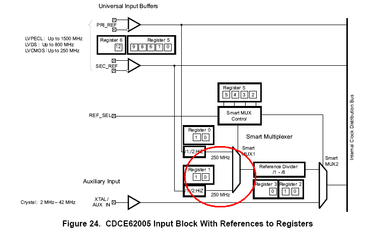
Other Parts Discussed in Thread: CDCE62005

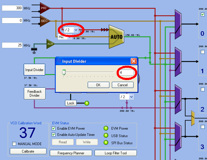
Setup with Fout= Fin.  For Fin=297MHz, calibrate function returns calibrate word=1 and output is not at correct frequency.  Is this a known issue?

When I toggle "enable evm power" check box in GUI correct output is observed.


  • Hello,

    we found a the same problem on our GUI and working on a solution for this problem
    and we released a new version of the CDCE62005 GUI. 

     http://www.ti.com/litv/zip/scac105e

    best regards

    Michael

  • Hi

    today we could archieve to reproduce your problem with the 297MHz Fin =Fout.
    The problem is the SMART Multipexer after the input section doesn`t work with more than 250MHz so he`s delivering not the right signal into the PLL loop.
    (more information on page 38 in the datasheet)


    to solve this behavior divide the inputsignal right after the buffer /2 and also sett the pre-divider of the PLL to the halv value.
    now the PLL will lock.

    best regards
    Michael

  • Issue still exists when input /2 pre-SAMRT mux is used.

    I withdraw this statement, it's not accurate.


  • Hi,

    Is this issue isolated to how the GUI was implemented?  Or is there a difference in the programming quoted in the datasheet?

  • Hi,

    the GUI was not invented to check this behavior.
    The data sheet shows the right values but there is no of these frequencies in the GUI.
    (but we note it to improof this)
    If this issue still exist then also some other things have to be checked:

    For single ended Input (LVCMOS) the maximum Frequency is 250 MHz
    Input Buffer should be selected to the used signal (LVDS or LVPECL)
    SMART MUX should select the input that`s used
    and also the Loop filter should be set to a common value -> Phase Margin between 45 and 70 Deg and Loop Bandwidth should be around 1/10 of the PFD Frequency.
    (this can be done with the internal Loopfiltercomponents)
    Maximum Clock Frequency Applied to Reference Divider 250MHz

    also the checkboxes in the GUI should be activated by changing this values: "enable EVM Power" and "enable Auto-Update-Timer" (the last option automaticalyl writes and reads the current setting into/from the EVM)

    in case a EVM is used also the PLL lock condition should be the same as selected in the GUI,
    also to get more qualitative measurements it`s recommended to power the EVM externally with 3.3V (also switch the  Jumpers while using external supply)

    If you share the used signal types for in and output and desired frequencies i offer you to create a .ini file.

    best regards
    Michael