This thread has been locked.

If you have a related question, please click the "Ask a related question" button in the top right corner. The newly created question will be automatically linked to this question.

A problem with PLL 'LMX2531LQ1500'.

Other Parts Discussed in Thread: LMX2531

Hi, dear all,

I met a problem with PLL 'LMX2531LQ1500'. I have two same boards with a PLL and clock buffer on them and the PLL and clock are all configured by FPGA. The PLL in the first board is working well. When the second board came, we use the same FPGA codes and we test the clock input, LE and CE all meet requirements, but there is no output. So we thought may be some thing wrong with the PLL chip and replaced it by a new one. But it's still the same thing. Also we cut off the output(to clock buffer) and extend the output to ground with a 49(Ohm) resistor, there is still no output.

(Further, the two PCB boards have the same layout but produced by different PCB companies. I do not think it would make any difference)
We can not figure out other ideas to fix this, can you kindly  give some advice?

Thanks so much!

Su

  • Su,

    Maybe this is related to the LMX2531 soldering.  Consider these 2 points:

    1.  THe LMX2531 package footprint is not symmetrical, which could lead to issues if soldered incorrectly.  When we went to lead free solder, we had a lot of problems, but most of these soldering issues are cleard now.  For soldering issues, other than visual inspection, look at current.  Also, the VregVCO pin should be 2.65 volts when powered up and the OSCin pin should be at Vcc/2 bias levels.

    2.  Make sure that the board house did not rotate the package.


    Regards,

    Dean

  • Dean,

    Thank you so much for you reply. 

    We tried many ways and there is no results. This problem block our whole project for a long time. 

    we have two same PCB boards, but produced by different companies. the old one works fine but the new one not. 

    Recently I test the whole condition about this pll chip, and the test results showed below:


    1. There is no output. 

    It shows that R counter works fine, but N counter not. 


    2.  testing the power input pins:
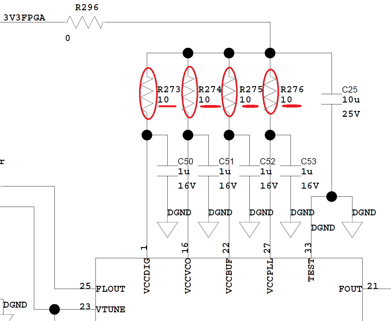
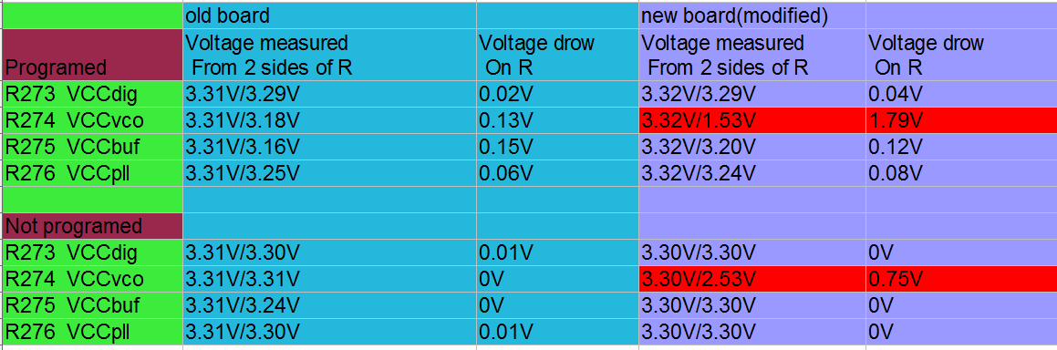
    our schematic showed below.  the VccVCO input to the pin of PLL is just 1.7V, which is out of the required value. Since the risistor R274 is 10 ohm, the current through it is about 0.17A. You said we should concern about the current, is this related to soldering? In fact, after X-ray, we have already check all pins should have already been connected 
    properly. 
    measurement results:
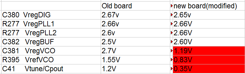
    3. The other pin's voltages

    You said Vrdg VCO should be 2.65V, BUT is not an input pin, how to control this value? 
    Thank you so much!