


hi all,
I get a strange question when i test my CDCE62005.
here i have four BOARD, A, B ,C ,D. A and B was same; C and D was same。
they all have the same configuration:
REF_SEL was set to PRI_CLK;
PRI_CLK = 10MHz;
VCO = 600MHz;
OUTPUT DIVIDER = 60;
OUTPUT = 10MHz.
and i want to sent the output of A to the input of B,and sent the output of B to C, and the input of D was from the output of C. and i did!
but the OUTPUT of B was not 10Mhz,however the output of A was 10MHz.
so i get some test:
1. test the output of A,B,C,D, when the input was float . and get what was happening at POWER ON.
2. test the output of A,B,C,D, following 1,sent a 10MHz at input.
3. test the output of A,B,C,D,and there was a 10MHz on the input whenthe boards was power on.
the result was strange。
1. A and C have not output, but B and D get 10Mhz(actually it was 10.1Mhz or 9.87MHz) frequency at the output pins.
2. A and C get 10MHz output,but B and D get another frequency around 10MHz(9.8Mhz or 10.2MHz ..)。
3. they all get 10MHz putput。
when i looks insight of the wave of power on,i find that A and B have a 40MHz at beginning。
here i get some image:
1. the output of A,B,C,D in TEST1
A:  B:
B: C:
C: D:
D: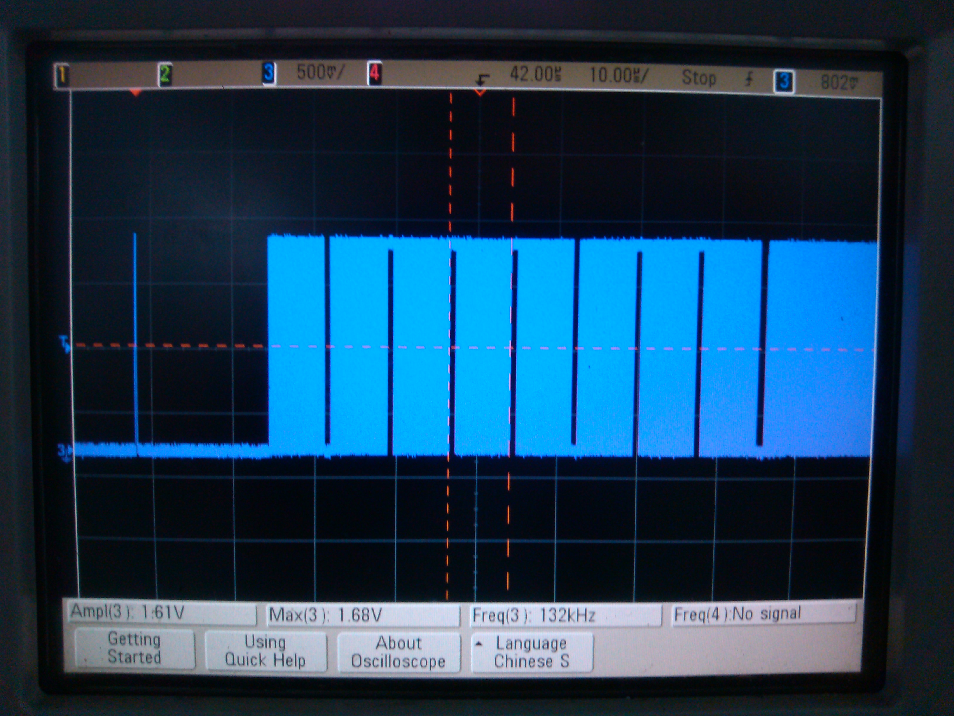
the image of A,it was a 40MHz signal. and A was AC COUPLING.
3: the output of A,B,C,D in TEST3
A: C:
C:
so it was the question:
1. why i get a 40MHz signal form output?
2. why i get a output frequency without input?
3. how can i make all the boards get the same status with C?
Thanls~