This thread has been locked.

If you have a related question, please click the "Ask a related question" button in the top right corner. The newly created question will be automatically linked to this question.

LMX2581 PLL does not lock

Other Parts Discussed in Thread: LMX2581, LMX2581EVM, CODELOADER, USB2ANY

Hello,

I've purchased the LMX2581EVM which works fine. But now i have integrated the LMX2581 in my own design. I used the schematics from the Eval board (Rev. C), except the unwanted parts (DNP parts: open; 0R0 Resistors: bridged). I ordered a PCB (FR-4) and tested my board. But the PLL just doesn't lock in...
I used the same part values as the LMX2581EVM and nearly the same layout. I checked my board numerous times and everything fits the LMX2581EVM. May the FR-4 be the problem? Or is there another possible reason why it won't lock?

Best regards

  • Hi Chris,

    First of all, are you able to control your board? That is, does the uwire interface work? If not, then try use Codeloader to control your board.

    Next question to you is, did you solder the GND paddle of the device? (pin 0, DAP)

  • Hi,

    Yes I am able to control the board via Codeloader and USB2ANY.

    Yes I soldered pin 8, pin 9, pin 18, pin 21, pin 0 (DAP), pin 27 and pin 31 to GND like in the LMX2581EVM.

    The problem is that the output frequency is not stable. It differs slowly from the programmed frequency until a varying difference and then hops back.

  • Hi Chris,

    Set the LD_SELECT bit (R7[12:8]) to R/2, see if you can see a stable clock at the LD pin (pin 25). the clock freq is equal to PDF/2. This test is to verify if the OSCin signal is got thru to the R-counter.

    Next set this bit to N/2, if the PLL lock, you should also see a stable clock with the same freq. In this case, since your output is not stable, I expect you will see a non-stable clock here.

  • Hi,

    Thank you for your help.

    I did as you told me. But I can see a stable clock in every case. R/2 and N/2 show my 10 MHz reference at LD pin. R/4 and N/4 show the half (5 MHz) at the LD pin.

    My output is still unstable. After I programm for example 400 MHz output. My spectrum analyzer shows me that the output starts at about 400.25 MHz and then slowly increases its frequency with approximately 1 kHz per second. This happens for all output frequencies and powers no matter if I use RFoutA or B.

    I've also set the LD pin to Vtune and recognized that the LD pin is then always at about 2.9 V. Could that be the problem? Where may that come from?

  • Hi Chris,

    you were saying that your OSCin freq is 10MHz, R/2 returns also 10MHz clock? If your PDF freq is 10MHz, you should see 5MHz with R/2 setting and 2.5MHz with R/4 setting. 

    Your output is drifting but you got stable N/2 clock at LD, this does not make sense as N/2 output follows VCO. If your VCO is drifting, N/2 will also be drifting. Furthermore, Vtune voltage of 2.9V does not seem correct.

    Would you provide your codeloader configuration and loop filter values to me?

  • Hi Noel Fung,

    yes sorry forgot to tell you that the doubler is active. So 10 MHz and 5 MHz would make sense.

    The unstability is about some kHz at 400 MHz and i measured N/2 with an oscilloscope, which isn't very precise in frequency. But I've measured N/2 now with a spectrum analyzer and it shows me that it is unstable aswell. It shows the same behaviour as my output. It slowly differs from its setpoint.

    The Vtune voltage also made me suspicious.

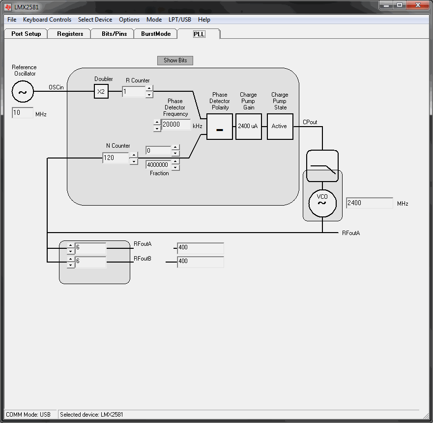
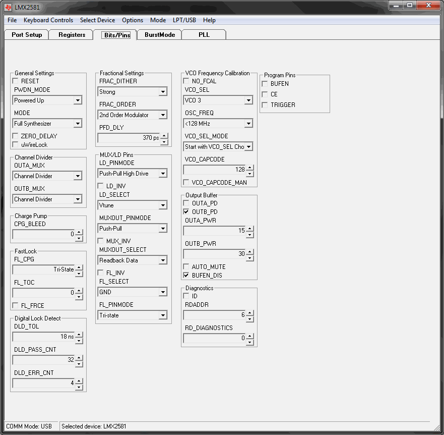
    Here is my codeloader config:
    PLL tab:

    Bits/Pins tab:

    I've changed LD_SELECT of course for the measurements.


    And here are the Registers:

    R5 (INIT) 0x00108005
    R15 0x021FE80F
    R13 0x4082C10D
    R10 0x210050CA
    R9 0x03C7C039
    R8 0x207DDBF8
    R7 0x00082237
    R6 0x000004C6
    R5 0x0010A805
    R4 0x00000004
    R3 0x2009E3E3
    R2 0x2FD09002
    R1 0xC4002011
    R0 0x40780000

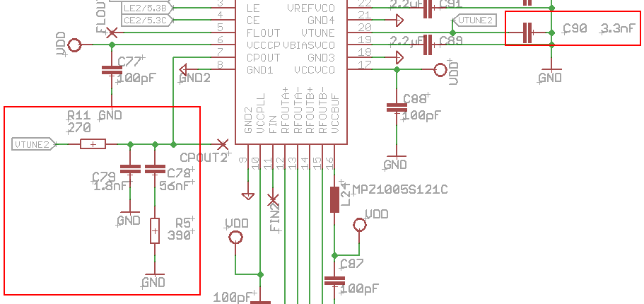
    And here is my loopfilter (taken from the LMX2581EVM):

  • Hi Chris,

    The register and loop filter look fine.

    Where is your 10MHz reference clock came from? Is it a sinewave or square wave? if it is a sinewave, try to increase its amplitude (increase its slew rate).

    Last trial is to set FRAC_DITHER to disable and FRAC_ORDER to integer. BTW, can you lock it at 2700MHz?

  • Hi Noel Fung,

    I'm sorry for the late reply. I was on the road since now.

    I tried different sources as reference. One source is the DG1022 Function/Arbitrary Waveform Generator from RIGOL. With that i tried both sine and square wave with various amplitudes. The other source I tried with is a SML 03 signal generator from Rhode & Schwarz. With that i also tried different amplitudes aswell as different frequencies. But i never achieved to lock the PLL.

    I just tried to disable FRAC_DITHER and set FRAC_ORDER to integer. But i can't lock it neither at 2700 MHz nor at any other frequency.

    Do you have any other ideas?

    Thank you in advanve and for your help so far.

    Best regards

  • Hi Chris,

    Your register configuration looks good, assuming your schematic and pcb layout have no error, also your input clock is fine, then I am really run out of idea. The very last assumption I have is the part has problem. Try to replace it and see how it works.

  • Chris,

    I'm not sure what is going on either, but it looks as thought the VCO is calibrating to the proper frequecy, but then the frequency drifts upward.   Realize that this device has a negative coefficient VCO, which means that if you put lower tuning votlage, the frequency goes up.  For instance, if your oscilloscope probe is a 50 ohms to ground, this could load down the loop filter and cause the VCO to go to higher frequencies.  During calibration, thie loop filter is switched out, so this would not impact the VCO calibration.


    Regards,

    Dean