


Hi,
I know that many questions have been posted about CDCE62005. Still, I want to post my own.
I tested the configuration parameter that provided my TI ,they comes :
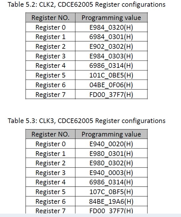
Then , the two CDCE62005 can generate all kinds of clocks like 312.5M,100M,66.667M on my C6678EVM board.
Unfortunately , when I changed some divider parameters, the CDCE62005 can't generate the clock frequency that I want . Here is one of my configuration parameter table :

What I supposed to get is 25M clock in the U0 channel ,62.5M clock in the U2 channel and 156.25M clock in the U3 channel , where the input for the CDCE62005 is 25M crystal in the AUXIN pin. However, the result is U0=25M,
U2 = 54.3M,U3=136M , then I tried to change Reg7 to FD00_37F7, the output keeps unchanged. How could this happens? Could you please help me to figure out the parameter ?
Best regards.
Philly.
