This thread has been locked.

If you have a related question, please click the "Ask a related question" button in the top right corner. The newly created question will be automatically linked to this question.

LMK03000C Series

I've been working with the LMK03033C, but I haven't been able to lock it, I have been using 20 and 40  Mhz clock inputs by adjusting R divider to be at (200,400) respectively (Targeting a 100 khz at the phase comparator), I am able to see the Rdivider frequency through PLL_MUX=11, but not the Ndivider, LMK is being driven single ended, AC coupled by .1 uF capacitors. I have reviewed http://e2e.ti.com/support/clocks/f/48/t/248734.aspx?pi196085=1, and tried to visualize the data stream coming into the device, and it seams correct, each clock cycle lasts at least 250 ns, while LE has been adjusted to 1 us, to ensure correctness.

I have also checked the Voltage signal, it is at 3.4V with a 20-30 mv ripple. Upon configuring the LMK it always seems that the internal VCO frequency is at  2230 Mhz, since the VCO divider is configured at 3, and individual clock lines are divided by 234. At lines 4, and 7 the output is 2.2258;hz, I can adjust the divisors and see that there is a frequency change on those lines. I am able to test the Reset command (since the clock lines become off), the R0 through R7 (due to the clock dividers), am also able to test R9 since Vboost amplfies the signal comming out of lines 4 and 7. Further more I can configure PLL_MUX located at R14, since I can see through the LD pin the Rdivisor frequency (around 50.003 in my case), but I'm unable to see the Ndivider output. 

I repeated the before mentioned procedures on 2 mounted PCBs with the same result, Could I be missing something here?

And Of course my programming sequence

R0  0x80000100 =initial Reset
R0 0x00000100  =Disable Line 0
R1 0x00000101=Disable Line 1
R2 0x00000102=Disable Line 2
R3 0x00000103=Disable Line 3
R4 0x0003A704=Enable Line 4, Clock Divider=334, Clock Mux=divided
R5 0x00000105=Disable Line 4

R6 0x00000106=Disable Line 6
R4 0x0003A707=Enable Line 7, Clock Divider=334, Clock Mux=divided
R8 0x10000908=Calibration
R9 0xA0032A09=Vbust=1
R11 0x0082000B=Div4=0
R13 0x0285800D= .OSCin_FREQ=20 VCO_C3_C4_LF=0; VCO_R3_LF=0; VCO_R4_LF=0;
R14 0x0890C80E = PLL_R=200, EN_CLKout_Global=1; EN_Fout=0; PLL_MUX=9
R15 0x0C18380F= PLL_CP_GAIN=0;VCO_DIV=3; PLL_N=6200

  • Hello,

    What are your external loop filter values (C1, R2, C2)?  If possible, could you send the portion of your schematic with the LMK circuitry for review? 

    Is your reference clock at OSCIN stable before R15 is programmed to initiate the VCO calibration routine?

    Regards,
    Alan

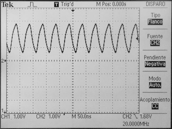
  • First of all thank you for your interest, as mentioned earlier I'm driving the OSCin single ended by a LVCMOS level oscillator, which seems stable during R15 programming, as seen on fig 1.


    Fig. 1 Input signal coming into OSCin.

    Now, C1=0, C2=100pF, R2=600k, before programming R15 the CPout signal is observed in figure 2.

    Fig. 2 CPout signal before calibration routine

    After issuing R15, CPout becomes active and does some kind of frequency sweep.

    Fig. 3 CPout signal during calibration routine

    One important thing to notice is before issuing R15 the VCO frequency seems to be at 1895 Mhz (Given VCOdivider=2, Individual Clock line=500), after issuing R15 the VCO frequency goes to around 2223 mhz.

    Figure 3. Before R15 issuing

    Figure 4 After R15.

    FInally I've uploaded my relevant PCB and Diagram for inspection, C11 in diagram is C2 on LMK datasheet, R2=R2, One final note C11 and R2 don't have the specified populated values, they are 600K and 100 pF.5672.ADC_MODULE_PCB2.pdf

  • Although this is very old, I see it is flagged as not answered. I am having almost exactly the same problem. I am using the TI Evaluation Board for the LMK03033C. I am feeding it 50MHz at +3dBm intoOSC_in. I am setting PD frequency to 2MHz, and using the MUX I see 1MHz on the LD pin when set to the R divider output. The N divider output is low, high or at 115 kHz. The Fout is either not present or at various frequencies between 1.6 and 2.2 GHz. I am trying to run the VCO at 2.16 GHz.
    I have set the internal loop filter components to the values suggested in the EVM users guide on P33.
    I wonder if this problem was ever solved? If so, how?
  • Are you seeing this issue on more than one board? Any possibility for solder-down issue?

    73,
    Timothy
  • I found the issue- it was a grounding problem. One of the PTH's on my micro board was not ground as I had assumed.

    Thanks for the reply.

    Gordon