This thread has been locked.

If you have a related question, please click the "Ask a related question" button in the top right corner. The newly created question will be automatically linked to this question.

CDCE925 Software Issue

Other Parts Discussed in Thread: CDCE925, CLOCKPRO, CDCE913

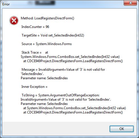
I have a design using the CDCE925 that has been in production for a few years.  Most boards work fine.  A handful have an issue communicating with TiClockPro.  I have attached a screenshot of the error message.  I get this error when the software is first launched, and then once within the application.  After the second time I get an even longer cryptic message and then the software crashes. 

If I load the software with a "good" board I can get to a point where the good board communicates fine.  Then I power the board down, disconnect the i2C cable and connect the "bad" board.  I am able to program the device but get an error message complaining about Fvco out of range and do I wish to modify N, M, P, and Q to generate the nearest valid Fvco.  I programmed the parameters used on all the "good" board so I am not sure what parameters are off. If I press No, it just pops up the same error in an infinite loop.  If I press "Yes" I just get the same error message as before.  I know the device gets programmed because the clock changes. 

Any insight into this oddity?

Thanks.

  • Hello Marco,

    can you please clarify which hardware you refer to when you write "Most boards work fine"? You have several evaluation modules like this?

    I recommend the following flow (where I assume you take the "good board" as reference for your modifications):

    1) start ClockPro, wizard window: press skip

    2) select "local CDCE925"

    3) enter your input frequency, press ignore if a dialog shows up

    4) ensure "live update" and "limit ranges mode" are unchecked

    5) connect your good board ("refresh devices" at the bottom and "read from device" at the top)

    6) do the modifications (when changing N,M,P,R try also to use the calculator symbol button)

    7) when everything is set up, swap to the other board then "refresh devices" and "write to device"

    Another recommendation is to set up everything in a "local CDCE925" (=software memory) and then transfer to the device with "live update" unchecked.

    Best regards,

    Patrick

  • These are custom boards for an application in digital audio.  We have made several thousand boards and most work fine.  I have a couple that are experiencing this problem.  We like to root cause all issues. 

    Using version 1.2 of the TI software I followed your suggestion but I can't get past step 5.  When I press refresh the software only shows 4 "Local" listings, not the connected hardware. 

    I unchecked the two items in step 4, loaded a saved configuration file, and then programmed a board giving me the issue.  I can see with a scope that the selected frequency is indeed programmed to EEPROM (remains after a power cycle).  However, it still throws these extra error messages.  Therefore the boards may work in my application, but since the is this anomaly we have to treat them as defective. 

    It would be nice to know why these errors occur other than simply calling these devices defective and discarding them.  Again, we like to know root cause.  So if you have any insight into what these error messages mean then that would help.  Thanks.

  • Hello Marco,

    the software issue is related to the automated consistency crosschecks running in the background of the GUI. For a detailed debug you would have to share the exact flow when this error happens for you including the full configuration of your device. Meanwhile when you feel insecure using the EVM software, I suggest you use a microcontroller or FPGA at your disposal to initiate the I2C transfer of the settings to the devices on your application board. The software allows to save various text formats which should help you to get the devices programmed. Please feel free to attach your settings to a post or send them to me directly for the software issue.

    Best regards,

    Patrick

  • Hello Patrick,

    The config file was sent via email.  Basically I hook up our product that has the TI chip on it.  Our board is "passive" with no micro or FPGA on it.  When I hook it up all I provide is power to the board which powers the chip and connect the i2C lines.  Nothing else is on the board that requires i2C. 

    I then start the TiClockPro software.  After I press "skip" and the GUI starts up I get the " Fvco out of range" error message.  Pressing "yes" produces the error in the attachment.  I have tried setting my parameter manually vs. using the config file with no difference.  I also tried "Go Default" to see if I could reset the device but still receive the error.  It seems anytime the GUI reads from the device it throws the second and third error boxes I sent you via email.

    Thanks

    Marco

  • Hello Marco,

    I received your e-mail! Thank you very much for describing the flow to me. I will come back to you about the findings.

    Best regards,

    Patrick

  • Hello Marco,

    can you please share the software version which you currently use? V1.2.1? Did you save the file using that version or do you still have it from an older revision?

    Moreover: can you please let me know your input frequency? (not part of the saved info)

    Which level is applied to the S0 pin in your application?

    Thanks!

    Best regards,

    Patrick

  • Version 1.2.  I downloaded the latest as a troubleshooting step.  Not sure which version the config file was saved under.

    Input frequency is:  24.576 MHz, source = VCXO.

    I didn't do the schematic.  It appears SO is floating.  Programming is done through S1 and S2 only. 


    Thank you for your help.

    M


  • Hello Patrick,

    I replaced the chip with a new one and the problem went away.  So it looks like an IC specific problem.  I have 2 boards with this issue (now 1). 

    Other than calling it a defective part, any insight into the error messages?

    Thanks

    Marco

  • Hello Marco,

    thanks for providing the info as much as possible.

    I tried to recreate your issue by preparing an EVM using your settings as EEPROM content. Then I tried various ways to get the error messages. So far I was unable to see those.

    I am unsure as the file name which you sent was for a CDCE913 device.

    What I could find so far points to the following happening:

    In the CDCE(L)913 datasheet you will find a table about the I2C addresses of all the devices of the clock generator family. As you know the last two bits of the slave address are reconfigurable using EEPROM bits as well. Which means software-wise we cannot perfectly detect which device we communicate with as soon as any bit of the EEPROM deviates from the factory default.

    All the three error messages you provided to me are following on each other.

    The first error about the "direct register form" is basically that the software thinks it is talking to a CDCE(L)925 while in reality it is a CDCE(L)913 hardware. The software tries to read higher register offsets which in reality are not there. So it ends up in an unhandled "out-of-bound" error. (we walk through all register offsets and now we get garbled info as the offset is an unexpected value).

    Now the automated consistency checks kick in as the values are propagated within the software to the various edit boxes, check boxes and so forth. As from the I2C we receive a binary stream of data it can happen that the value mismatches with the bounds of the GUI equivalent where each of them has its own boundary limits.

    What I can state is that any bits which you read or write from the device will be ok, as long as it fits together.

    For example, let's assume you prepared a configuration for a CDCE925 and you program it into a CDCE913. That is ok as the register map is the same. The higher offsets, which are not existent in the CDCE913, will not harm the matching bits.

    When you prepare a CDCE913 configuration and you load it into a higher grade device you only programmed a subset of what you can configure. But the settings you transferred will have the effect which you expect.

    Any issues which might come on top because of a device defect are a different story and we would have to take a look separately (if you would like to get the unit analyzed).

    Moreover one additional issue which can come into play: when you connect the EVM to your application board. The EVM is designed to provide good setup and hold margins for the I2C (for the capacitance of the EVM). When you connect it to another board using cables the setup and hold times might degrade and this may influence the communication as well. I assume anything below 10inches should be ok. Maybe you can crosscheck the slew rates close to the device?

    Best regards,

    Patrick

  • Hello Patrick,

    We saw a few more board have this issue so I am up to 7 total.  I wrote a simple MFC/Visual Studio app to read and program all the registers, so I can use this app instead of TiClockPro to program the devices in production.  With this app I am able to confirm that the address bits remain the default 0xca for the 913 device.  Once I program the device I tried to verify the programming via the TiClockPro but am getting the same error messages as before (which also crashes the TiClockPro app).  The output from my program has the registers set to:

    Register 0x00 ...   0x81
    Register 0x01 ... 0x05
    Register 0x02 ... 0x36
    Register 0x03 ... 0x00
    Register 0x05 ... 0x50
    Register 0x06 ... 0x40
    Register 0x14 ... 0xed
    Register 0x16 ... 0x01
    Register 0x17 ... 0x00
    Register 0x18 ... 0x4e
    Register 0x19 ... 0x20
    Register 0x1a ... 0x83
    Register 0x1b ... 0x4c
    Register 0x1c ... 0x00
    Register 0x1d ... 0x40
    Register 0x1e ... 0x02
    Register 0x1f ... 0x08


    I am OK with proceeding with my app and not using the TiClockPro software, but I would like to make sure there isn't something more fundamentally wrong with the device that my program isn't catching.  As far as I am concerned, the devices seem to work and can be programmed with my application, but these 7 boards still have an issue with the TiClockPro software.  So I can't release my software if there is indeed a hardware issue with these boards that my software can't detect.  Or, perhaps these errors are not that important.  Do you have thoughts beyond what you mention above on what could still be causing the error messages?

    Thanks

    Marco


  • Hello Marco,

    would it be possible to send us one of those boards to take a closer look? Our software is made for the EVM and I am unsure which sensitivities might come in because the unit is in the board. I would like to take a look and also check on the unit details.

    Best regards,

    Patrick

  • Hello Patrick,

    Yes, I can send you a board.  To power the board you need 3.3V and 5V (<20mA each).  I can solder pig tails for each access to power lines.  I can also provide a header cable for the i2C (programming port).  Would this be OK? 

    Please send me your address via my email.  I think you have this?

    Thanks!
    Marco