This thread has been locked.

If you have a related question, please click the "Ask a related question" button in the top right corner. The newly created question will be automatically linked to this question.

LMX2581 Fastlock function

Other Parts Discussed in Thread: LMX2581

Hello

I would like to know the function of the Fastlock in the LMX2581.


1. How to decide the value of the R2pLF in the table 9 Fast lock configuration of the Data

sheet ?

- Although the table give user way of calculating K, it is difficult for beginner. Please let me

have an example for calculating process.


2. How much Lock time it has between Normal mode and Fastlock Mode


Thanks and Best Regards

  • Hi Jin,

    I think you have the old datasheet, pls download the latest one from our website. Fast lock calculation is available in section 8.3.10.

    theoretical lock time improvement is equal to 100%/K. Fine tune the value of FL_TOC register value for optimum lock time.

  • Hello

    The inforamtion of the Fastlock is listed on the latest data sheet section 8.3.12.

    According to the formula of table 9. Fastlock configuration, K=sqrt(FL_CPG/CPG). How much value user decide for FL_CPG and CPG?

    8.6.1.10.1 CPG and 8.6.1.7.4 Fast lock CPG have value range from 0 to 31. Does user select one value range from 0 to 31?

    What values user have to use for calculating K?

    Please let me have expample for getting K.

    Thanks and Best Regards

  • Jin,

    The value of K is based on the fastlock current ratio.  For instance, if I was to use fastlock, you might set the charge pump to 8x gain (CPG=8) for normal operation and 31x gain for fastlock operation (FL_CPG=31x).  In this case, K=sqrt(31/8) ~ 2.   The resistor R2p is R2/ (sqrt(2) - 1).  So R2p = R2 in this case. 

    In this case, the loop bandwidth would be twice during fastlock and the lock time wuld theoretically be half.  However, the actual improvement would less because of the VCO digital calibration and fastlock disengagement glitch.  So maybe a 20% reduciton in lock time.  For cases with a wide loop bandwidth and a lock time that is fast, say < 1 ms, you might not see any improvement.  For cases with a more narrow loop badwith and slower lock time, say >10 ms, they you would probably see more than 20% improement.


    Regards,

    Dean

  • Dean

    My customer is interested with lock time. According to your answer, CPG is the most important thing for lock time.

    I Would like to know the below

    1. If user place lock time on priority first,  Does user set the highest values 31 for CPG and FL_CPG?

    2. If CPG and FL_CPG, both of them are 31 for focusing on Lock time, what performances are trade-off on there?

    3. Additionally, except CPG values, what factors are affecting on Lock time?

    4. This is because, the customer expects lock time is below 200uS and target change frequency switch 1088MHz to 1252.5MHz. is the 200uS be realized?

    Thanks and Best Regards

  • Jin,

    In regards to your question:

    1.  FL_CPG should be set to 31.  However, for fastlock to work, you need to use a lower current when not in fastlock, like CPG=8.  If you use the lower CPG value, there might be some phase noise degradation relative to CPG=31 but this is the cost of using fastlock.

    2.  FL_CPG must be greater than 31 for fastlock to be useful.

    3.  For lock time, there are the elements of the VCO calbration time and the analog lock time.

    The VCO calibration time can be anywhere from 10 us to 200 us, depending on setup.  The two things you can do to speed this up is increase the OSCin input frequency and also program the device to get the VCO caibration close.  I would focus on minimizing this as it costs no performance degadation and might be more effective.  To do this, you need to estimate what core and frequency to go next to.   For 1088 MHz, this is in the middle of VCO core 1, so set VCO_SEL=VCO1 and VCO_CAPCODE= 128.   When switching to 1252.5 MHz, this is in VCO Core 2, abut 2/3 of the way up, so set VCO_SEL=VCO 2 and set VCO_CAPCODE = 95.  I am getting this from table 5 on page 19 of the datasheet.   Set the VCO_SEL_MODE = "Start with VCO_SEL choice".

    As for the analog lock time, since your lock time is pretty fast anyways, you might find that Fastlock is not nearly as helpful as the VCO calbiration trick above.  Also, it will cost you phase noise.   This is because the Fastlock creates a glitch when disengaged that has to settle out.  There is still a benefit to it in cases with longer lock times, but for this 200 us lock time, I think there might not be.   For the analog lock time, a wider loop bandwidth would probably be more beneficial and the higher charge pump current will improve the performance.  When designing for wider bandwidths, one of the restrictions is that the capacitors get too small, and this is where the charge pump current is better to be large.

    So in conslusion, if I was the customer, I would use a higher input reference, use the method to speed up the VCO calibration, and design for a wider loop bandwidth with the highest charge pump current. 

    Regards,
    Dean

  • Dean

    First of all, thank you for your answer. It helps me understand Locktime operation.


    I would like to re-check your answer "2.FL_CPG must be greater than 31 for fastlock to be useful."

    According to data sheet of LMX2581, the Maximum value of FL_CPG is 31. How can set the FL_CPG is greater than 31?


    I have question, If set GPG is 31, is the PLL operated as Fastlock always?

    As long as I know between the CPG and ICP, if the value of GPG is 31, ICP is maximized.


    Thanks and Best Regards

  • Jin,

    Indeed, FL_CPG is set equal to 31, not greater than 31.  Although we allow FL_CPG to be progrmmed to anything, I have never seen a situation where it makes sense to use anything less than the maximum value.

    The difference between enabling fastlock with FL_CPG=31 and just setting CPG=31 all the time is that the state of the FLout pin is grounded with the fastlock and not so with just setting CPG=31.  Other than this it is the same.

    Regards,

    Dean

  • Dean

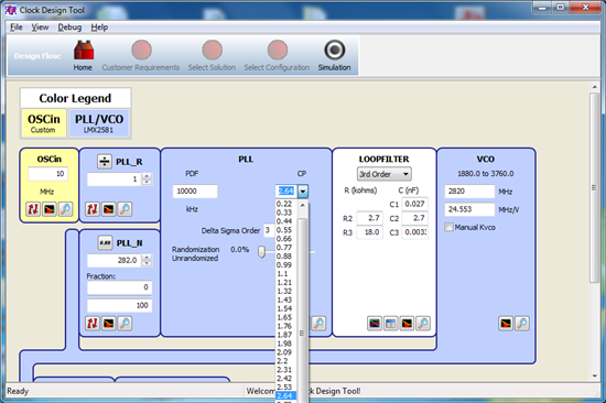
    For using the function of fast lock, setting FLCPG = 31 but I can not select a Optimozed CPG value.

    I am trying to design PLL by using Clock design tool, http://www.ti.com/tool/clockdesigntool.

    It helps user have values of loop filter but it does not give value of CPG. How can user find a optimized CPG value?

    Please let me know.

    Thanks and Best Regards


  • The charge pump gain can be selected in the "PLL" block.  The lowest state is CLG=0 and the highest state is CPG=31.   For an optimized value, the highest gain is best for phase noise.  Clock Design tool defaults to the 24x state to allow some margin if one wants to adjust the charge pump gain to accomodate for changes in VCO gain.  If you want to use Fastlock, use the 8x state, whic corresponds to 0.88 mA, but I personally would just use the highest charge pump gain all the time and not use fastlock.  Instead, use the trick to speed up the VCO Calibration.


    Regards,

    Dean