This thread has been locked.

If you have a related question, please click the "Ask a related question" button in the top right corner. The newly created question will be automatically linked to this question.

Questions - using LMX2492 ...

Other Parts Discussed in Thread: LMX2492EVM, LMX2492, USB2ANY, LMX2492-Q1

Hello Simon.

I'm interested in LMX2492EVM, because I need chirp generator for the source of FMCW radar system.

a few questions...

1. What is the upper and lower limit for ramp duration ? (I want to control ramp duration)

2. How fast can I sweep frequency? (=delta F/delta T)

3. Which one should I choose - Sawtooth/Flat Top Triangle/Complex Triggered Ramp to make this signal ; ?


      (I think Complex Trigger Ramp waveform is not exactly linear chirp(little bit curved).)

Thanks you. 

  • Dear JongSeop,


    Thank you for your questions.

    1) The length of the ramp is controlled by the Field RampX_len (where X=[0:7] for each ramp) and set the duration in number of phase detector cycle. this is a 16 bit number and the Field RampX_dly can double this value. the minimum will simply be one phase detector cycle.  Note that the speed at which the VCO change frequency is ultimately defined by the loop bandwidth of the PLL and hence step function in frequency can push the loop out of lock and also cycle slipping. see section 9.2.3 of the D/S for a good example.

    2) the ramp slope is ultimately limited by the loop bandwidth. Our EVM loop bandwidth is rather large and allow for fast sweeping. You will also have to make a tradeoff with ramp accuracy versus speed.

    3) the triangular wave you are looking for can be generated with only 2 states. Our D/S has numerous example that will help you to generate this triangular wave. Also, the software for our EVM has a GUI that helps you calculate the actual register/field values for your desired ramps duration[us]/frequencies[MHz].

    Hope this helps, Simon. 

  • Thank you for Answer Simon.

    Before buying LMX2492(qty=2), I want to know whether it is proper source for FMCW Radar.

    our targets are ;

    1.to get  center frequency=3GHz(S Band), delta F=600MHz, ramp duration=20us. triangular ramp

    2. to get center frequency=10GHz(X Band), delta F=1.5GHz, ramp duration=50us. triangular ramp

    I downloaded CodeLoader4 and simulated ramp generation. But I got few problem.

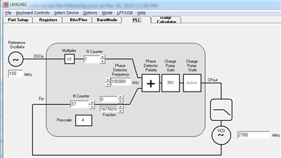
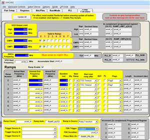
    Question 1. After setting PLL Tab and Ramp Calculator shown below,


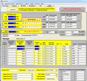
    I check [options]-Enable Flex Scripts, and click [Update All]. Then, all numerical values I set automatically changed shown below... :(

    Why this happened?

    Question 2.  There are three VCO Output port - Direct VCO Output, VCO/2 Output, VCO/4 Output.

    2-1)If Direct VCO Output is 10GHz, is VCO/2 Output 5GHz, VCO/4 Output 2.5GHz ?

    2-2)Can I use these three VCO Output ports simultaneously?

    Question 3. 3-1) If I bought LMX2492_eval, I think I need more stuffs to operate whole system. - XO(for F_oscin), 5V Supply, Computer(for USB2ANY Connector). is it right? (three stuffs.) Then, Should I always bring computer to operate lmx2492?

                          3-2) Are connecting cables involved?

    Question 4. I read on D/S that N-counter should be greater than 16. why? (Because I need fPD=200MHz & N=13.5 to get VCO output 2700MHz)

    PS. I'm beginner at RF engineering, so it's little bit hard to understand... 

           could you please reply soon? thank you!

  • Hello,


    thank you for your questions.


    1) the flex script update based on the default value in the actual register/field. Youcan then change to your dsired setting.

    2.1) yes

    2.2) yes

    3.1) yes that is correct check the user's guide for the actual hardware required.

    3.2) I beleive cables are included with your kit..

    The road of RF is a fun road, enjoy the journey!


    Regards,

    Simon.

  • Thank you for your answer Simon.


    From your answer 3.1)..., so, I should always bring my note book/desktop computer when I use it? ... too heavy..;;


    And I have another question.

    Question 1. In lmx2492_eval D/S page 5, loop filter configuration is shown.

    I'm little bit confused that in Table 2-1, VCO Frequency, Phase Detector Frequency, and OSCin Frequency are fixed value-9.4-10.1GHz, 100MHz, 100MHz,

    respectively. I understood these values can be chosen for user. How can I understand it?

    Question 2. 2.1) I want to know VCO Output power for S ,X band ramping (3GHz, 10GHz). Can you tell me Output power(dBm) versus S, X band Frequency?

                         2.2) additionally, how much are variations for output power?

    Question 3. 


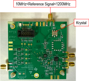
    I captured above figure from your video. If we set external reference signal, why is on chip Krystal needed? What is role of on chip Krystal?

    Question 4. What is difference between LMX2492 & LMX2492-Q1 ?

  • Hello

    you are quite right the frequency are user defined with some min-max value based on the IC performance.

    The LMX2492 does not output any signal from the VCO. The output power you get is from the VCO. So if you were to use an other VCO, the output power will depends upon the VCO you use.

    The EVM is designed to meet different needs. If an external referecne is sued, then the on board XO is not needed. and vice versa.

    The Q version of this product meets the requirements for automotive applications.

    Regards,

    Simon.