Hi
I have TI's Excel spreadsheet PLL Calculations.xls to help me calculate Loop filter parameters. When I input the following:
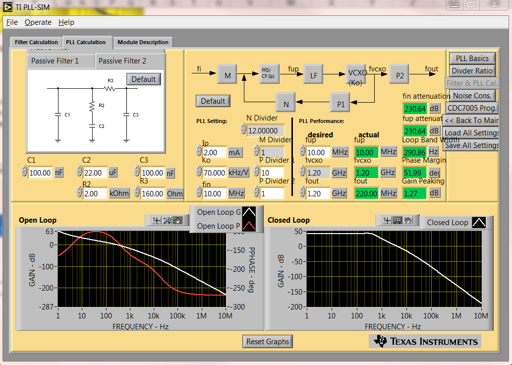
Fc=1.2GHz
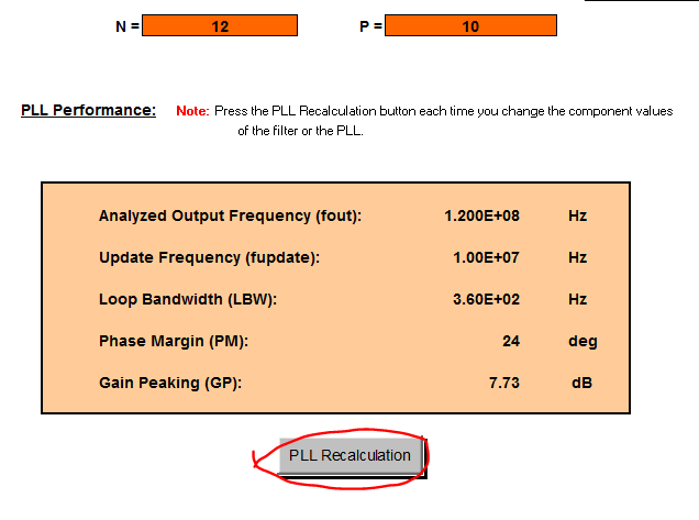
P=10 N=12
M=1
Fref = 10 MHz
Ko=70 kHz/V
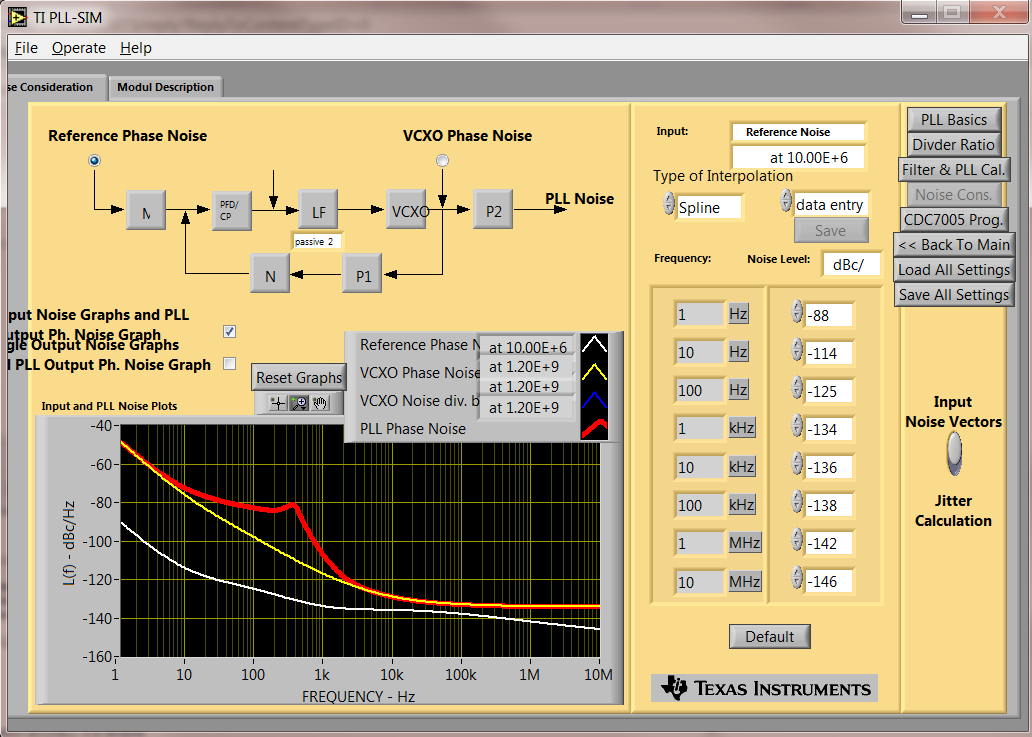
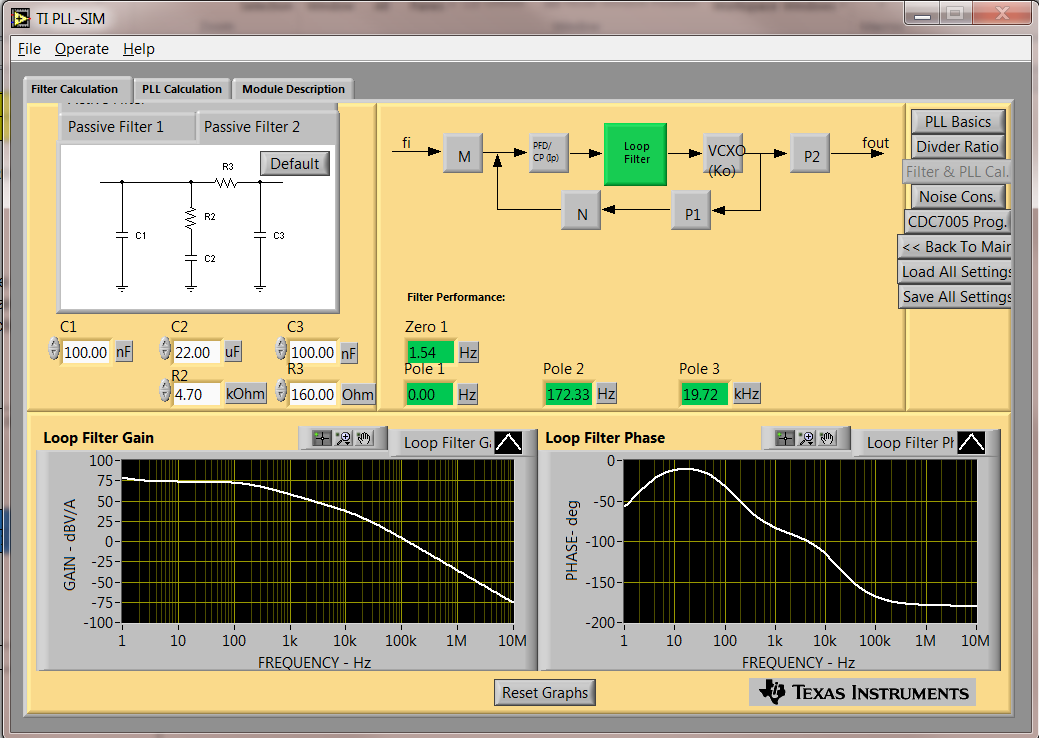
I get an analyzed Freq out of 14.4GHz, and a 22uF capacitor (c2) a LPW of 360 PM of 24 deg, etc I would expect a lower LBW using a 22 uF capacitor.
What am I looking at and is this the right tool?
Could you explain the fields?