This thread has been locked.

If you have a related question, please click the "Ask a related question" button in the top right corner. The newly created question will be automatically linked to this question.

LMX2581, balun or direct

Other Parts Discussed in Thread: LMX2581, LMX2581EVM

Hi,

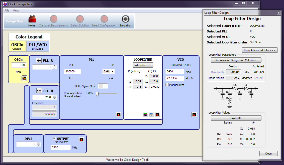
we are evaluating LXM2581 for a project that will need only a carrier frequency at around 2.4GHz, 0dBm to an 50ohm antenna via an smc connector.

I have some questions;

1) how well would it work to connect the antenna directly to one of the diff pins on LXM2581?

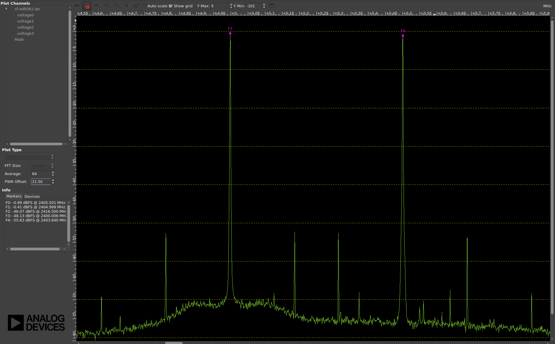
2) is it possible to use a balun directly with LXM2581, and if so, how would that improve signal quality? (not power, rather signal integrity, phase noise etc.)

Thanks in advance,

Mike

  • Mike,

    In response to your questions;

    1.  Never tried this, but it should work.  Remember that the other unused side should be terminated to avoid high harmics on the side you are using.  The output impedance is set by the pull-up component.   So you could use either the 50 ohm pull-up, or if you use an inductor, put a pad afterwards.  The power can be programmed a lot higher than 0 dBm, so you do have some power to burn if you have to.

    2.  We have tried a balun on the LMX2581 and it works fine, altough it does not improve the phase noise or spurs. 


    Regards,

    Dean

  • Dean, thanks for you answer!

    I will try both direct and via balun and will report back results if anyone else is interested.

    This is my first design with lmx2581, so i have probably got something wrong. Any suggestions to improve the design is most welcome!

    Thanks in advance,

    Mike

  • Makael,

    A few comments on the Schematic:

    1.  For the OSCin pin, it looks like you copied what we have on our evaluation board.  This is good for a CMOS output pin at 3.3 V, but this network might change for other inputs.

    2.  For the Vtune pin, the part likes to see a lower impedance to ground as seen from this pin or it can cause bumps in the VCO phase noise.   3.3 nF is what we recommend, but you can push to 1.5 nF, but 33 pF that you have is really low.   We have a section in the datasheet describing this.  To increase this capacitor, you can:

    a.  Use a second order filter or reduce the T3/T1 ratio for the 3rd order filter

    b.  Use the highest charge pump current

    c.  Use the highest possible phase detector frequency

    d.  Reduce the lop bandwidth.


    REgards,

    Dean

  • Dean,

    thanks again for a prompt and illuminating reply.

    Yes, we have a cmos buffer for the ref clock. I just redesigned the buffer to use 1V8, it will hopefully will reduce emi.

    I was also surprised of the values produced by the clock design tool. Perhaps i should do the math myself. Here's a slightly modified design in the clock design tool,  still very high impedances i think:

    Why does it recommend such high impedance?

    Is gerber files of LMX2581EVM available somewhere? I only found gerber files for TSW16DX370 EVM. I'm curious on how you did the design for the termination there, but It's difficult to see from SNAU136C.pdf.

    Thanks in advance,

    Mike

  • Hi,

    just want to confirm that this is the proper way to drive an (50Ω) antenna direct from lmx2581, before i send to board house.

    Any suggestions are most welcome.

    Thanks in advance.

  • Mikael,
    Yes, this looks good to me, although I do think that the 10 pF cap is a little bit small. The output impedance is set by the pull-up component. Also be sure that R401 is close to the pin for the best output power.
    Regards,Dean
  • Hi Dean,

    thanks a lot!

    Regards,
    Mike

    PS. I should mention that our first prototype was built with a competing product (stw81200). Reason for scrapping that solution was total lack of support and documentation. I can't express how satisfied I am with our choice to go with TI. Your support and documentation is great. Many thanks! :-)

  • Thanks for all help Dean!

    We have been through a bit of testing, and we're on the right track. Driving direct without balun seem just fine, and there's more power than we'll ever need.

    The following sweep indicates that phase noise is not yet optimal (F1=LMX2581, F0=AD9361 reference design). I have been tweaking loop filter and register settings and can't get it much better than this. I suspect that our clock synth suffer from jitter however. We use 100MHz frequency to LMX2581 and the mul x2 feature. The aim is to do better than the AD9361, which i suppose is possible. Does this look like ref clock jitter to you?

    Thanks in advance,
    Mike

  • Mikhael,

    For the best jitter on this device, assuming integer mode, you want hte max phase detector frequency and charge pump gain.  It looks like your loop bandwidth is about 50 kHz and maybe it could be a little wider, but it seems reasonable what you have.

    I see a lot of spurs, but it looks like you might be clocking  an A/D, so maybe it is related to that.

    Regards,

    Dean

  • Hi Dean,

    we are forced to use fractional mode for application reasons, so that is what i'm trying to optimize.

    Yes, both charge pump gain and phase detector frequency is maximized. I found that 2nd order modulator with some charge pump bleed works best in our design. Indeed, 50KHz bandwidth was used, will try to make it a bit wider, thanks! I have tried both 2nd, 3rd and 4th order loop filter, and 3nd order seem to give lowest phase noise. Is that expected?

    Considering that we are bound to fractional mode, do you think there's room for improvement?

    Thanks in advance,
    Mike

  • Mike,
    I can't be sure as I don't know the input and output frequencies, but what you say seems reasonable. Have you tried our new PLLatinum Sim tool? You can search our website for "PLLatinum Sim" and this will do simulations for loop filter, phase noise, and fractional spurs.

    With the loop filter for this device, you also have to watch out that the capacitor next to the VCO does not get too small, or else there is some VCO phase noise degradation in the 100-200 kHz range. This is discussed in the datasheet.

    Regards,
    Dean