


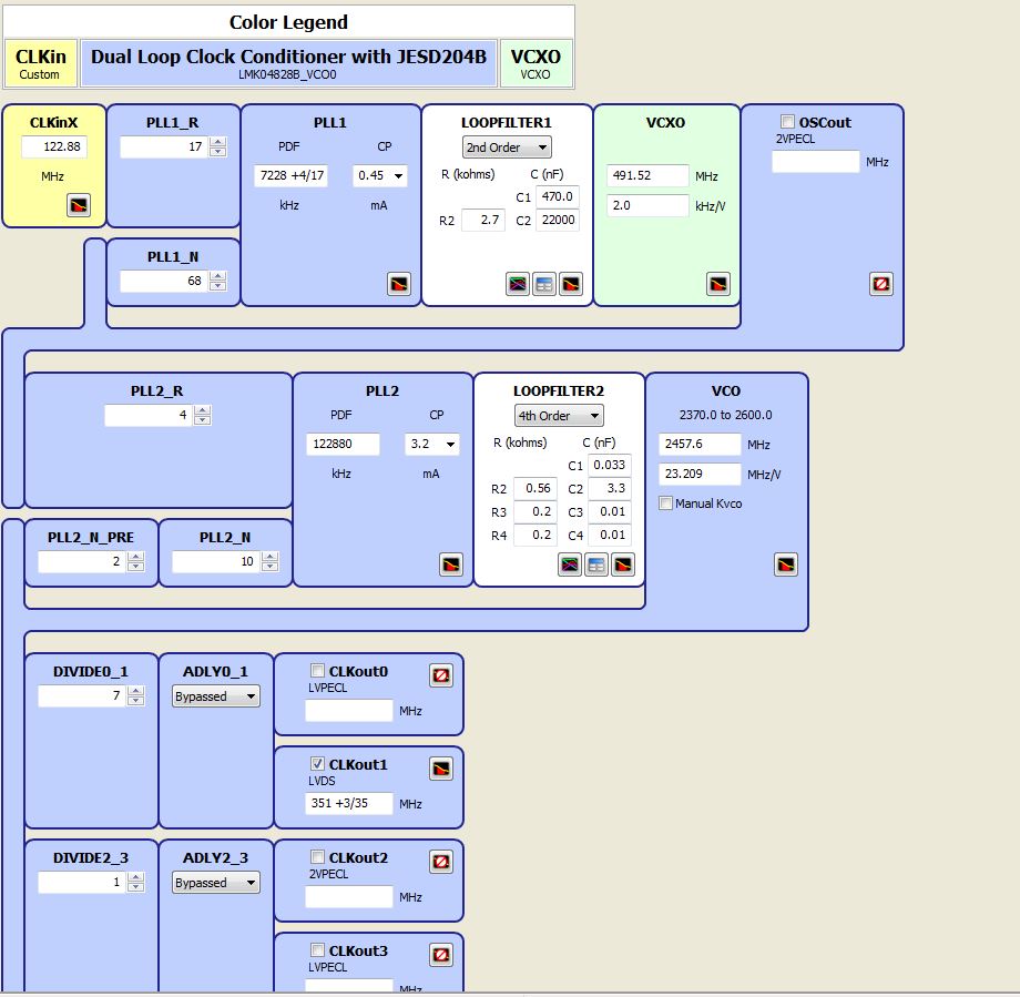
I am trying to use coadloader to load the spi interface of the LMK04828B device. I am also using the DAC3xJ8x gui v1,.1 software to confim. I have attached all my files where I simulated the clock to be ~351MHz, and how I have things hooked up. I have a 122.88MHz crystal input that generates the 351MHz output. The problem is SDCLK and DCLK should be the same and coadloader is not making them the same. Which divider did I miss or what am I doing wrong?
Regards
R0 (INIT)	0x000090
R0	0x000010
R2	0x000200
R256	0x000001
R257	0x000055
R259	0x000002
R260	0x000020
R261	0x000000
R262	0x000070
R263	0x000011
R264	0x000001
R265	0x000055
R267	0x000002
R268	0x000020
R269	0x000000
R270	0x000070
R271	0x000011
R272	0x000001
R273	0x000055
R275	0x000002
R276	0x000020
R277	0x000000
R278	0x000070
R279	0x000011
R280	0x000001
R281	0x000055
R283	0x000002
R284	0x000020
R285	0x000000
R286	0x000070
R287	0x000011
R288	0x000001
R289	0x000055
R291	0x000000
R292	0x000020
R293	0x000000
R294	0x000070
R295	0x000011
R296	0x000001
R297	0x000055
R299	0x000000
R300	0x000020
R301	0x000000
R302	0x000070
R303	0x000011
R304	0x000001
R305	0x000055
R307	0x000000
R308	0x000020
R309	0x000000
R310	0x000070
R311	0x000011
R312	0x000040
R313	0x000003
R314	0x000000
R315	0x000007
R316	0x000000
R317	0x000008
R318	0x000003
R319	0x000000
R320	0x000000
R321	0x000000
R322	0x000000
R323	0x000051
R324	0x0000FF
R325	0x00007F
R326	0x000018
R327	0x000040
R328	0x000002
R329	0x000002
R330	0x000002
R331	0x000016
R332	0x000000
R333	0x000000
R334	0x000000
R335	0x00007F
R336	0x000003
R337	0x000002
R338	0x000000
R339	0x000000
R340	0x000078
R341	0x000000
R342	0x000011
R343	0x000000
R344	0x000096
R345	0x000000
R346	0x000011
R347	0x0000D4
R348	0x000020
R349	0x000000
R350	0x000000
R351	0x00000B
R352	0x000000
R353	0x000002
R354	0x000045
R355	0x000000
R356	0x000000
R357	0x00000C
R380	0x017C15
R381	0x017D33
R358	0x000000
R359	0x000000
R360	0x00000A
R361	0x00005D
R362	0x000020
R363	0x000000
R364	0x000000
R365	0x000000
R366	0x000013
R371	0x000000
R8189	0x1FFD00
R8190	0x1FFE00
R8191	0x1FFF53
Andrew1108.pll2_config.cfg
